Air Bleed
impossible to make the engine idle with any adjustment because
the air draft in the carburetor at low idle is too weak to lift
the fuel from the jet to the throttle.
If it were only necessary for the suction to draw fuel through
the jet opening, (J) the mixture proportion would be uniform at
all speeds; but the deficiency below 16 m.p.h. is due to the fact
that some of the suction force must be exerted in raising the fuel
from the level in the float chamber up to the jet outlet: to avoid
overflow with the engine not running, the jet must necessarily
stand a safe distance above the float level.
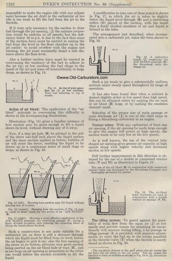
Also a further suction force must be exerted in overcoming the
tendency of the fuel to adhere to the jet tip; at low suctions
the fuel clings to the metal of the jet and tears off intermittently
in large drops, as shown in Fig. 14.
Action of air bleed: The application of the "air bleed" principle
in overcoming this difficulty is shown in the accompanying illustrations.
Illustration (Fig. 15) gives a familiar instance of how suction
may be great enough to lift a liquid above its level, without drawing
any of it away.
Now, if a tiny air hole (B) be pricked in the side of the straw
one-half inch above the liquid surface and the same suction applied
as before, bubbles of air will enter the straw, enabling the liquid
to be drawn up in a continuous series of small slugs or drops,
as shown in Fig. 16.
Fig. 15 (left). Showing how suction may lift liquid without drawing
any of it away.
Fig. 16 (center). Showing how the suction of Fig 15 may be made
to draw ' iquid, by the action of an "AIR BLEED" B).
Fig. 17 (right). Showing a more effective application of the AIR
BLEED principle (by restricting passage 0), giving a finely divided
emulsion, and reducing the retarding effect of lifting the liquid
above its level.
Such a construction is not quite suitable for a carburetor jet,
as there is still a distance through which the liquid must be lifted
from its level, before the air begins to pick it up; also the free
opening of the straw at its bottom prevents very great suction
being exerted on the air bleed hole or vent (B), just as too large
an air opening in proportion to the straw size would reduce the
suction available to lift the liquid.
A modification to take care of these points is shown in Fig. 17,
in which the air is taken in slightly below the liquid level through
(B) and a restricting orifice (0) placed at the bottom, with the
result that a finely divided emulsion of air and liquid is formed
in the tube.
The arrangement just described, when incorporated into a carburetor
jet, takes the form shown in Fig. 18.
Such a jet tends to give a substantially uniform mixture under
steady speed throughout its range of operation.
It has also been found that when a mixture is desired slightly
richer at low speed than high speed, this can be obtained either
by waking the air vent or air bleed (B) large, or by making the
emulsion channel' small.
Selection of the proper size of main passage or main discharge
jet (J) is one of the chief steps in fitting a Stromberg carburetor
to an engine.
Venturi tubes: With any carburetor of fixed size air opening, if
the air opening be made large enough to give the engine full power
at high speeds, the suction tends to be very low at the low speeds.
As is well known, the use of the venturi tube shaped air opening
gives greater air capacity at high speeds along with higher velocity
and increased suction at low speeds.
Still further improvement in this direction is obtained by the
use of a double or compound venturi tube (V and VI) as illustrated
in Figure 19.
The use of the air bleed (B) in conjunction with compound venturi
tubes was developed by the Stromberg Company and thoroughly protected
by patent.
The idling system: To guard against the possibility of weak flow
from the main jet (J) at low speeds and provide means for obtaining
an exceptionally rich mixture (luring idling, a by-passage or idlirlg
passage (I) is provided, with separate adjustments, to carry the
fuel up to the intake manifold at the throttle valve (T) when the
throttle is nearly closed as shown in Fig. 20.
The emulsion channel is the part where the air enters the jet from
the air bleed to the jet outlet. The air causes the gasoline to
form in bubbles as shown in Fig. 18 at (J), termed an emulsion.
Fig. IS. A carburetor nozzle (J) employing the AIR BLEED principle
(B): the Stromberg main discharge jet.
Fig. 19. The air-bleed main discharge jet used in conjunction with
a double venturi air passage (V, VI).
FIG. IC c
Fig. 14. Ac.ion of plain gasoline jet (J) at low suctions. Note
fuel adhering to top of nozzle.
Previous page 1927
Supplement Home Next page 
|
