Stromberg
DYKE'S INSTRUCTION No. 88 (Supplement)
monel metal, which is harder and denser than the seat. As long
as the needle valve point stays round, it will also wear the
seat round so that no leakage will result.
On the Models "OE," "OA," "OS," and
some others, the strainer chamber is cast in one piece with the
bottom of the carburetor, while the float needle valve seat is
screwed in from the top. The strainer is then held in by a nut
screwed in from the bottom.
Gasoline Flow to Jets; Adjustments
Gasoline flow to jets: adjustments: From the float chamber, the
fuel is drawn to the main discharge jet.
The main adjustment for the high-speed mixture is furnished by
the high-speed adjustment needle, but at the request of certain
motor car manufacturers a gasoline reducer, or fixed size nozzle,
has been used in the carburetors furnished them as a means of preventing
the unskilled driver from getting too rich an adjustment.
The gasoline reducer is preferably made about two drill sizes larger
than the size of orifice which would give the right mixture if
the high speed adjustment needle were all the way out.
When the gasoline reducer is used, the high-speed adjustment in
actual use behaves peculiarly in that starting from an all the
way out position, as it is screwed down, it first seems to have
no effect at all, until its opening approaches the size of that
in the gasoline reducer, when it begins very gradually to take
effect; then as it becomes smaller than the gasoline reducer, it
takes effect very fast.
In cases where no adjustment of the high-speed needle will seem
to give the engine enough gasoline to run, it is well to see if
the gasoline reducer in the carburetor is too small.
The auxiliary gasoline adjustment is simply an-other high-speed
adjustment needle which can be operated from the dash and gives
an additional channel for gasoline to flow from the float chamber
to the main discharge jet.
On certain engines not equipped with hot-spot intake manifolds,
this control is thought to give a better warming up adjustment
than can be obtained with the use of the choke valve alone (see
also foot-note, page preceding).
Main Discharge Jet
The main discharge jet: After passing the adjustment orifices,
the gasoline flows to the central opening of the main discharge
jet (Fig. 24). This jet has a number of holes in its side, of
which the top ones—usually of considerable number and located
just under the head of the jet—admit the air bleed taken
past or through the point of the economizer needle.
The lower holes (see main discharge jet, Fig. 24) are smaller in
size and allow the fuel to feed from the center part of the jet
to the horizontal channel leading over to the idling tube.
The outer space around the jet is usually filled with gasoline
standing over these holes, which serves as a reservoir, from which
either the idling system or main jet system can draw during quick
changes in their relative suction, as the throttle is moved or
the load on the engine changed.
In some specifications the size and number of these idle feed holes
have been reduced to what is believedto be just sufficient to feed
the idle up to a point where the main jet begins to deliver. If
these holes are too small, it is still possible to get an idle
adjustment, but the engine will have a tendency to stall coming
back to idle, after the throttle has been opened to race the engine.
As previously explained, the size of the main discharge jet determines
whether the wide open throttle mixture is uniform at low and high
speeds or whether it will become somewhat leaner at the high-speed
end.
The size opening required for a uniform mixture should vary in
proportion to the amount of gas required, which in turn depends
upon the size of the large venturi.
In general, it is found that on the 1" carburetors a No. 34-18
main discharge jet (the No. 18 being the size drill in the body
of the jet and No. 34 the drill in the outlet tip) will give a
uniform low to high-speed pulling mixtures, while a No. 36-20 will
cause the mixture to lean out about as required for best performance
and by the majority of engines.
In the 1%" size a No. 26-18 will probably give a uniform mixture
range, while a No. 30-18 is more generally found best.
In the 1M" carburetor a No. 22-9 will give a uniform mixture,
while a No. 28-15 is customarily used as giving a mixture slightly
leaner at high speeds.
Air Bleed and Economizer Action
The air bleed: The air bleed (B) at wide open throttle, or high-speed
bleed is regulated by the size of the opening through the point
of the economizer needle valve (see N, Figs. 21, 22, page 1243,
and note white lines in end of needle), and is usually No. 56.
When the economizer needle valve does not seat securely, this will
give the effect of a considerably larger high-speed bleeder and
require more than the customary opening of the high-speed gasoline
adjustment at all speeds, and even then may be lean at high speed.
Fig. 25 (left). Details of the economizer action of the Model "O" carburetor.
By referring to Figs. 21 and 22, an idea as to how the economizer
needle (N) operates into the air bleed (B)-will probably make this
illustration clearer. A point to remember is that the economizer
needle itself has an opening in its point, as shown by the white
lines at (N).
At partial throttle opening, as shown in Fig. 25, the air-bleed
channel (B) is unrestricted by the economizer needle valve.
Fig. 25A (right). At full-throttle opening the air bleed is restricted
to the small opening in the taper needle point of (N).
The economizer needle is raised and lowered by action of the throttle
shaft.
PARTI:IL THROTTLE OPENING FULL THROTTLE
Previous page 1927
Supplement Home Next page 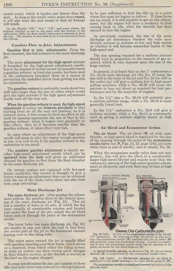
|