CARBURETORS: STROMBERG
CARBURETOR FLANGE THROTTLE VALVE
IDLE DISCHARGE JEt
IDLE ADJUSTMENT NEEDLE. HIGH SPEED ADJUSTMENT NEEDLE FLOAT NEEDLE
DRAIN MC
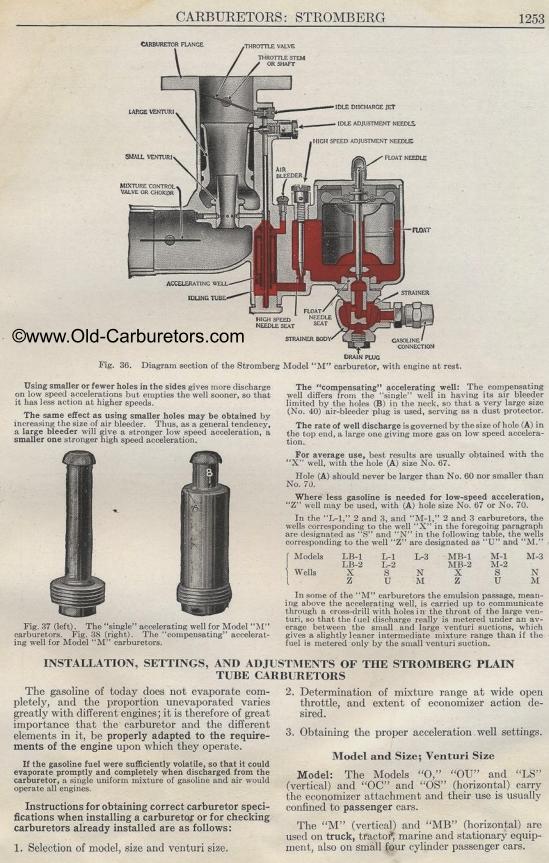
Fig. 36. Diagram section of the Stromberg
Model "M" carburetor,
with engine at rest.
Using smaller or fewer holes in the sides gives more discharge
on low speed accelerations but empties the well sooner, so that
it has less action at higher speeds.
The same effect as using smaller holes may be obtained by increasing
the size of air bleeder. Thus, as a general tendency, a large bleeder
will give a stronger low speed acceleration, a smaller one stronger
high speed acceleration.
Fig. 37 (left). The "single" accelerating well for Model "M" carburetors.
Fig. 38 (right). The "compensating" accelerating well
for Model "M" carburetors.
The "compensating" accelerating well: The compensating
well differs from the "single" well in having its air
bleeder limited by the holes (B) in the neck, so that a very large
size (No. 40) air-bleeder plug is used, serving as a dust protector.
The rate of well discharge is governed by the size of hole (A)
in the top end, a large one giving more gas on low speed acceleration.
For average use, best results are usually obtained with the "X" well,
with the hole (A) size No. 67.
Ilole (A) should never be larger than No. 60 nor smaller than No.
70.
Where less gasoline is needed for low-speed acceleration, "Z" well
may be used, with (A) hole size No. 67 or No. 70.
In the "L-1," 2 and 3, and "M-1," 2 and 3 carburetors,
the wells corresponding to the well "X" in the foregoing
paragraph are designated as "S" and "N" in
the following table, the wells corresponding to the well "Z" are
designated as "U" and "M."
Models LB-1 L-1 L-3 MB-1 M-1 M-3
LB-2 L-2 MB-2 M-2
Wells X S N X S N
Z U M Z U M
In some of the "AI" carburetors the emulsion passage,
meaning above the accelerating well, is carried up to communicate
through a cross-drill with holes in the throat of the large venturi,
so that the fuel discharge really is metered under an average between
the small and large venturi suctions, which gives a slightly leaner
intermediate mixture range than if the fuel is metered only by
the small venturi suction.
INSTALLATION, SETTINGS, AND ADJUSTMENTS OF THE STROMBERG
PLAIN
TUBE CARBURETORS
The gasoline of today does not evaporate completely, and the proportion
unevaporated varies greatly with different engines; it is therefore
of great importance that the carburetor and the different elements
in it, be properly adapted to the requirements of the engine upon
which they operate.
If the gasoline fuel were sufficiently volatile, so that it could
evaporate promptly and completely when discharged from the carburetor,
a single uniform mixture of gasoline and air would operate all
engines.
Instructions for obtaining correct carburetor specifications when
installing a carburetor or for checking carburetors already installed
are as follows:
1. Selection of model, size and venturi size.
2. Determination of mixture range at wide open throttle, and extent
of economizer action de-sired.
3. Obtaining the proper acceleration well settings. Model and Size;
Venturi Size
Model: The Models "0," "017" and "LS" (vertical)
and "OC" and "OS" (horizontal) carry the economizer
attachment and their use is usually confined to passenger cars.
The "M" (vertical) and "MB" (horizontal) are
used on truck, tractor, marine and stationary equipment, also on
small four cylinder passenger cars.
<
Previous page 1927
Supplement Home Next page 
|