CARBURETORS: CADILLAC
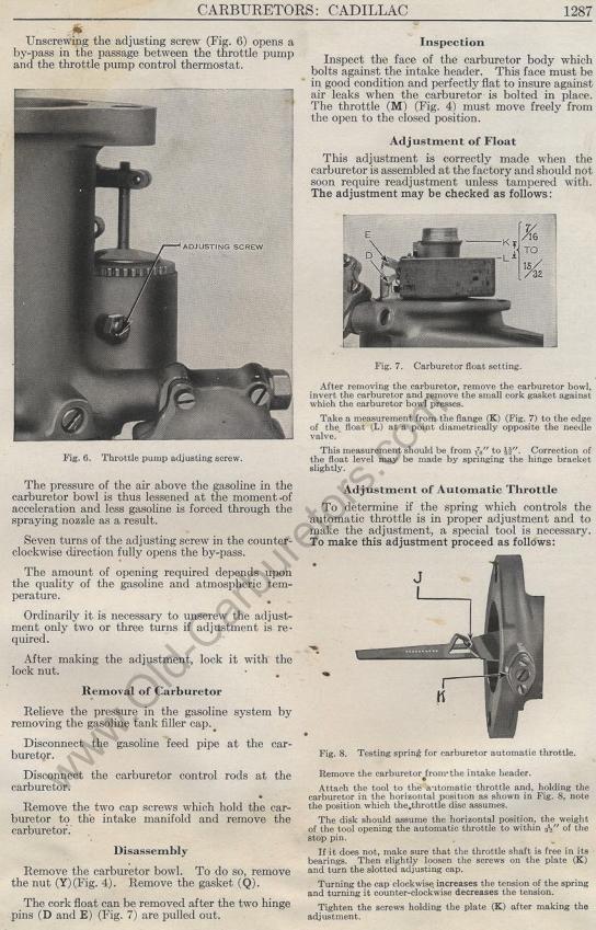
Unscrewing the adjusting screw (Fig. 6) opens a by-pass in the
passage between the throttle pump and the throttle pump control
thermostat.
Fig. 6. Throttle pump adjusting screw.
The pressure of the air above the gasoline in the carburetor
bowl is thus lessened at the moment .of acceleration and less
gasoline is forced through the spraying nozzle as a result.
Seven turns of the adjusting screw in the counter-clockwise direction
fully opens the by-pass.
The amount of opening required depends upon the quality of the
gasoline and atmospheric temperature.
Ordinarily it is necessary to unscrew the adjustment only two
or three turns if adjustment is required.
After making the adjustment, lock it with the lock nut.
Removal of Carburetor
Relieve the pressure in the gasoline system by removing the gasoline
tank filler cap.
Disconnect the gasoline feed pipe at the carburetor.
Disconnect the carburetor control rods at the carburetor.
Remove the two cap screws which hold the carburetor to the intake
manifold and remove the carburetor.
Disassembly
Remove the carburetor bowl. To do so, remove the nut (Y)(Fig.
4). Remove the gasket (Q).
The cork float can be removed after the two hinge pins (D and
E) (Fig. 7) are pulled out.
Inspection
Inspect the face of the carburetor body which bolts against the
intake header. This face must be in good condition and perfectly
flat to insure against air leaks when the carburetor is bolted
in place. The throttle (M) (Fig. 4) must move freely from the
open to the closed position.
Adjustment of Float
This adjustment is correctly made when the carburetor is assembled
at the factory and should not soon require readjustment unless
tampered with. The adjustment may be checked as follows:
Fig. 7. Carburetor float setting.
After removing the carburetor, remove the carburetor bowl, invert
the carburetor and remove the small cork gasket against which the
carburetor bowl presses.
Take a measurement from the flange (IC) (Fig. 7) to the edge of
the float (L) at a point diametrically opposite the needle valve.
This measurement should be from i„" to W. Correction
of the float level may be made by springing the hinge bracket slightly.
Adjustment of Automatic Throttle
To determine if the spring which controls the automatic throttle
is in proper adjustment and to make the adjustment, a special tool
is necessary. To make this adjustment proceed as follows:
Fig. 8. Testing spring for carburetor automatic throttle. Remove
the carburetor from-the intake header.
Attach the tool to the automatic throttle and, holding the carburetor
in the horizontal position as shown in Fig. 8, note the position
which the throttle disc assumes.
The disk should assume the horizontal position, the weight of the
tool opening the automatic throttle to within " of the stop
pin.
If it does not, make sure that the throttle shaft is free in its
bearings. Then slightly loosen the screws on the plate (K) and
turn the slotted adjusting cap.
Turning the cap clockwise increases the tension of the spring and
turning it counter-clockwise decreases the tension.
Tighten the screws holding the plate (K) after making the adjustment.
Previous page 1927
Supplement Home Next page 
|
