Zenith
Gasoline from the bowl flows through the compensating jet into
(I) (Fig. 19) into the idling well (W) and is then lifted by
the engine suction through the idling jet (P), which has a calibrated
opening at its upper end.
Air is measured through the idling needle valve seat in accordance
with the adjustment of the needle valve (0), Fig. 18. The mixture
of gas and air passes through the idling hole and on into the engine
cylinders.
To set the idle, get the engine thoroughly warmed up and then regulate
the engine idling speed by turning the throttle lever stop screw
(A) in lock nut (B) until the throttle butterfly is opened enough
for the speed desired. At the same time manipulate the idle adjusting
screw (0) (Fig. 18 or 19) to get the right mixture.
Turning in on the adjustment screw (0) cuts off the air supply
and makes the mixture richer, while backing out the adjusting screw
admits more air and makes the mixture leaner.
When a satisfactory idle has been obtained, securely lock the throttle
lever stop screw (A) in place by means of the lock nut (B) which
is attached to throttle lever (Y).
For normal idling speed, the needle valve (0) should be backed
out from closed position to from a to 1z turns.
Air connection: The air intake (Fig. 17) is provided with an air
strangler valve which is operated by the driver through the "choke" rod.
When closed tight this valve serves as a strangler for starting
and when only partially closed, it en-riches the mixture for warming
up.
Particular care should be taken to insure the strangler butterfly
opening fully, and closing tight, when actuated by the control
rod.
Starting the engine: When cold, open the throttle "just a
crack" and have the dash choke control clear out or at "closed" position.
Immediately the engine starts, push choker in part way, and as
the engine warms up, move the control gradually in or toward the "open" position.
When engine is hot, it should not be necessary to use the choke
control at all. Remember that running with the choke in a partially
closed position greatly increases the fuel consumption.
Care of the carburetor: Keeping the carburetor free from dirt and
water is the only care necessary.
The important parts to be cleaned are the filter screen (Dl), the
main jet (G), and the compensating jet.
To clean the filter screen, take off the filter plug at the bottom
of the bowl with a wrench, remove the union body (D), and pull
out the filter screen. Clean the screen with gasoline, or compressed
air, and be sure that it has no holes when replaced.
The main jet and the cap jet can be unscrewed when the lower plug
and the compensating jet plug on the side have been removed.
If you wish to clean the idling jet (P) (Figs. 17 and 19), remove
the screws which hold the bowl to the barrel, and then unscrew
the jet. Use compressed air or gasoline to clean the jets. Never
use a wire.
The carburetor can be taken completely apart and put together again
without danger of disturbing the adjustment. Simply be careful
that all gaskets are in place and the screws and jets drawn up
snugly.
When ordering parts, always give name of part, model number of
carburetor, and in addition, the name and model of car on which
carburetor is used.
It is important to specify the size of the chokes or jets desired.
If there is any doubt as to requirements, give full details as
to name and model of car, size of engine, (bore and stroke), number
of cylinders, size of choke and jets now in carburetor and any
installation difficulties which may be apparent. (Manufacturers,
Zenith )
Fig. 17. Section showing barrel and air intake of model SV Zenith
carburetor (ST is similar; see footnote,2 page 1297). Fig. 18.
Section showing bowl and float mechanism of model SV.
Names of parts: A, throttle stop screw; B, throttle stop screw
lock nut; D, gasoline line union nut; D1, gasoline s.,rainer; F,
float; Fl, float arm; F2, float arm axle; F3, needle valve collar;
G, main jet; G1, float needle valve; 0, idling adjustment; P, idling
jet; S, float needle valve seat; W, idling tube; X, venturi; Y,
throttle lever.
Previous page 1927
Supplement Home Next page 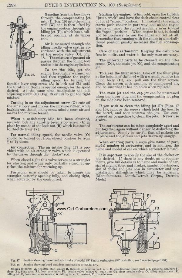
|