PACKARD CARBURETOR: Model 426-433
Construction; Adjustments
PACKARD CARBURETOR (Model426-433)
The Packard carburetor as used on the 426-433
six-cylinder car and 336-343 eight-cylinder car is similar in principle of operation
to previous models, as explained on page 140. The carburetion mixture
is heated and vaporized by means of an exhaust heated intake manifold.
Gasoline System
General principle: The gasoline supply of 21 gallons is carried
in the main tank at the rear of the frame. From there it is drawn
to a vacuum tank on the dash by suction from the engine. From the
vacuum tank it flows to the carburetor by gravity.
Gasoline gauge: A gauge (the Grolan, similar to that shown in Fig.
16, page 650) is mounted on the instrument board to indicate the
amount of gasoline in the tank.
Gasoline filter: To prevent water and sediment from accumulating
in the carburetor, a gasoline filter is located below the vacuum
tank in a plainly visible position.
1 Refers t, six-cylinder cars (model 426-433). The model 336-343
eight-cylinder carburetor is similar.
3Carburetor
The carburetor is of the automatic float-feed air-valve type, with
a single stage spray nozzle and a cylindrical mixing chamber.
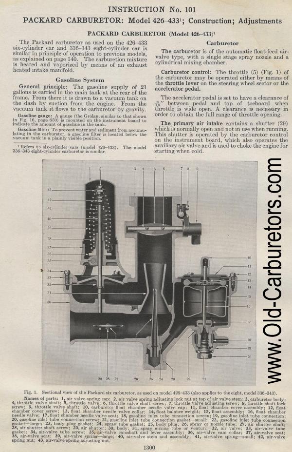
Carburetor control: The throttle (5) (Fig. 1) of the carburetor
may be operated either by means of the throttle lever on the steering
wheel sector or the accelerator pedal.
The accelerator pedal is set to have a clearance of
between pedal and top of toeboard when throttle is wide open. A
clearance is necessary in order to obtain the full range of throttle
opening.
The primary air intake contains a shutter (29) which is normally
open and not in use when running. This shutter is operated by the
carburetor control on the instrument hoard, which also operates
the auxiliary air valve and is used to choke the engine for starting
when cold.
c,
Fig. 1. Sectional view of the Packard six
carburetor, as used on
model 426-433 (also applies to the eight, model 336-343).
Names of parts: 1, air valve spring cap; 2, air valve spring adjusting
lock nut at top of air valve stem; 3, carburetor body; 4, throttle
valve shaft; 5, throttle valve: 6, throttle valve shaft screw;
7, throttle valve adjusting screw; 8, throttle shaft lock screw;
9, throttle valve shaft; 10, carburetor float chamber needle valve
cap; 11, float chamber cover assembly; 12, float chamber cover
screw; 13, float chamber needle valve collar; 14, float balance
weight; 15, float assembly; 16, float chamber needle valve; 17,
float chamber needle valve seat; 18, gasoline inlet tube connection
screen; 19, gasoline inlet tube connection; 20, gasoline inlet
tube connection screw; 21, gasoline inlet tube connection gasket—small;
22, gasoline inlet tube connection gasket—large; 23, body
plug gasket; 24, spray tube gasket; 25, body plug; 26, spray or
nozzle tube; 27, air shutter shaft; 28, air shutter shaft screw;
29, air shutter; 30, body; 31, spray mixing tube or venturi; 32,
air valve; 33, air-valve tube gasket; 34, air-valve tube screw;
35, air-valve camshaft and lever assembly; 36, air-valve cam collar;
37, air-valve seat; 38, air-valve seat; 39, air-valve spring—large;
40, air-valve stem and assembly; 41, air-valve spring—small;
42, air-valve spring nut; 43, air-valve spring adjusting nut.
Edit: Old cars needed more filters than we use now. I set up A1 Filters to preselect all the filters for sale on Ebay.
Previous page 1927
Supplement Home Next page 
|