Cadillac Old Carter Carburetors : CADILLAC V EIGHT 1942Previous | Home | Next |
 |
Form 6519—Canadian
1945 CADILLAC V EIGHT 1942
MODELS
"60S-61-62-63-65-75"
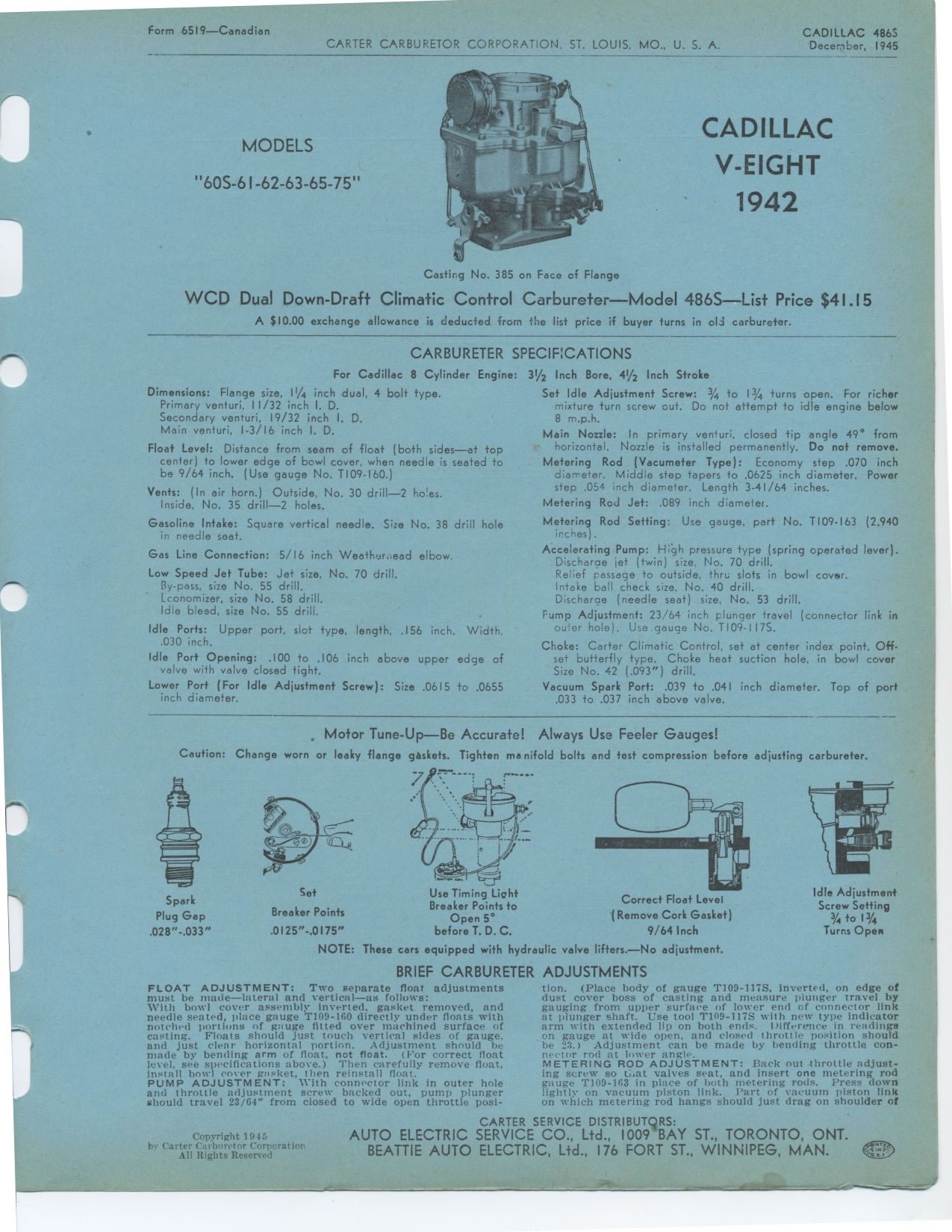
Casting No. 385 on Face of Flange
WCD Dual Down-Draft Climatic Control Carbureter—Model 486S—List
Price $41.15
A $10.00 exchange allowance is deducted from the list price if buyer turns
in old carbureter.
CARBURETER SPECIFICATIONS
For Cadillac 8 Cylinder Engine:
Dimensions: Flange size, 11/4 inch dual, 4 bolt type. Primary venturi, 11/32
inch I. D.
Secondary venturi, 19/32 inch I. D.
Main venturi, 1-3/16 inch I. D.
Float Level: Distance from seam of float (both sides—at top center) to
lower edge of bowl cover, when needle is seated to be 9/64 inch. (Use gauge
No. T109-160.)
Vents: (In air horn.) Outside, No. 30 drill—2 holes. Inside, No. 35 drill—2
holes.
Gasoline Intake: Square vertical needle. Size No. 38 drill hole in needle seat.
Gas Line Connection: 5/16 inch Weathur,.ead elbow.
Low Speed Jet Tube: Jet size, No. 70 drill. By-pass, size No. 55 drill.
Lconomizer, size No. 58 drill.
Idle bleed, size No. 55 drill.
Idle Ports: Upper port, slot type, length, .156 inch. Width, .030 inch.
Idle Port Opening: .100 to .106 inch above upper edge of valve with valve closed
tight.
Lower Port (For Idle Adjustment Screw): Size .0615 to .0655 inch diameter.
31/2 Inch Bore, 41/2 Inch Stroke
Set Idle Adjustment Screw: 3/4 to 13/4 turns open. For richer mixture turn
screw out. Do not attempt to idle engine below 8 m.p.h.
Main Nozzle: In primary venturi, closed tip angle 49° from horizontal.
Nozzle is installed permanently. Do not remove.
Metering Rod (Vacumeter Type): Economy step .070 inch diameter. Middle step
tapers to .0625 inch diameter. Power step .054 inch diameter. Length 3-41/64
inches.
Metering Rod Jet: .089 inch diameter.
Metering Rod Setting: Use gauge, part No. T109-163 (2.940 inches).
Accelerating Pump: High pressure type (spring operated lever). Discharge jet
(twin) size, No. 70 drill.
Relief passage to outside, thru slots in bowl cover. Intake ball check size,
No. 40 drill.
Discharge (needle seat) size, No. 53 drill.
Pump Adjustment: 23/64 inch plunger travel (connector link in outer hole).
Use gauge No. TI09-117S.
Choke: Carter Climatic Control, set at center index point. Off-set butterfly
type. Choke heat suction hole, in bowl cover Size No. 42 (.093") drill.
Vacuum Spark Port: .039 to .041 inch diameter. Top of port .033 to .037 inch
above valve.
. Motor Tune-Up—Be Accurate! Always Use Feeler Gauges!
Caution: Change worn or leaky flange gAskets. Tighten manifold bolts and test
compression before adjusting carbureter.
Spark Plug Gap ,028"-.033"
Set
Breaker Points
.0125"-.0175"
Use Timing Liqht
Breaker Points to
Open 5
before T. D. C.
Correct Float Level
(Remove Cork Gasket)
9/64 Inch
Idle Adjustment
Screw Setting
3/4 to 13/4
Turns Open
NOTE: These cars equipped with hydraulic valve lifters.—No adjustment.
BRIEF CARBURETER ADJUSTMENTS
FLOAT ADJUSTMENT: Two separate float adjustments must be made—lateral
and vertical—as follows:
With bowl cover assembly inverted, gasket removed, and needle seated, place
gauge T109-100 directly under floats with notched portions of gauge fitted
over machined surface of casting. Floats should just touch vertical sides of
gauge. and just clear horizontal portion. Adjustment should be made by bending
arm of float, not float. (For correct float level, see specifications above.)
Then carefully remove float, install bowl cover gasket, then reinstall float.
PUMP ADJUSTMENT: With connector link in outer hole and throttle adjustment
screw backed out, pump plunger should travel 23/64" from closed to wide
open throttle posi-
tion. (Place body of gauge T109-117S, inverted, on edge of dust cover boss
of casting and measure plunger travel by gauging from upper surface of lower
end of connector link at plunger shaft. Use tool T199-117S with new type indicator
arm with extended lip on both ends. Itifference in readings on gauge at wide
open, and closed throttle position should be 23.) Adjustment can be made by
bending throttle con-peeler rod at I svor angle.
METERING ROD ADJUSTMENT: Back out throttle adjusting screw so ti at valves
seat, and insert one metering rod gauge T109-163 in place of both metering
rods. Press down lightly on vacuum piston link. Part of vacuum piston link
on which metering rod hangs should just drag on shoulder of
Copyright 1945