Cadillac Old Carter Carburetors : CADILLAC V 16 1938 1939 1940Previous | Home | Next |
 |
Form 6321 B—Canadian
CADILLAC 4075-4085
March, 1938
Reprinted July. 1944
CAR SERIAL NUMBERS
5270001 and Higher
NOTE: CARBURETER 407S USED ON LEFT
SIDE OF MOTOR; 408S ON RIGHT SIDE.
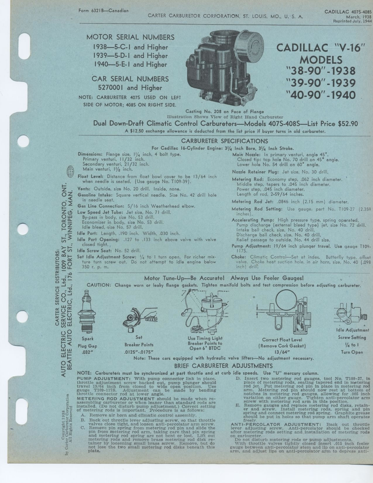
Casting No. 208 on Face of Flange
Illustration Shows View of Right Hand Carbureter
Dual Down-Draft Climatic Control Carbureters—Models 407S-408S—List
Price $52.90
A $12.50 exchange allowance is deducted from the list price if buyer turns
in old carbureter.
CARBURETER SPECIFICATIONS
MOTOR SERIAL NUMBERS
1938—5-C-I and Higher
1939—5-D-I and Higher
1940—5-E-I and Higher
CADILLAC V 16
MODELS
38 90 1938
39 90 1939
40 90 1940
31/4
For Cadillac 16-Cylinder Engine: Dimensions: Flange size, 11/4 inch, 4 bolt
type.
Primary venturi, 11/32 inch.
Secondary venturi, 21/32 inch.
Main venturi, 11/g inch.
Float Level: Distance from float bowl cover to be 13/64 inch when needle is
seated. (Use gauge No. T109-39).
Vents: Outside, size No. 20 drill. Inside, none.
OZ Gasoline Intake: Square vertical needle. Size No. 42 drill hole Q in needle
seat.
Gas Line Connection: 5/ 16 inch Weatherhead elbow.
Low Speed Jet Tube: Jet size, No. 71 drill. By-pass in body, size No. 53 drill.
Economizer in body, size No. 53 drill.
• Idle bleed, size No. 57 drill.
Idle Port: Length, .190 inch. Width, .030 inch.
Idle Port Opening: .127 to .133 inch above valve with valve closed tight.
Idle Screw Seat: No. 52 drill.
Set Idle Adjustment Screw: 1/4 to I turn open. For richer mixture turn screw
out. Do not attempt to idle engine below 350 r.
Inch Bore, 3¼ Inch Stroke.
Main Nozzle: In primary venturi, angle 45°. Closed tip: top hole No. 70
drill on 45° angle. Lower hole No. 54 drill on 60° angle.
Nozzle Retainer Plug: Jet size, No. 30 drill.
Metering Rod: Economy step, .062 inch diameter.
Middle step, tapers to .045 inch diameter.
Power step, .045 inch diameter. Length of rod, 2-59/64 inches.
Metering Rod Jet: .0846 inch (2.15 mm) diameter.
Metering Rod Setting: Use gauge, part No. T109-27 (2.359 inches).
Accelerating Pump: High pressure type, spring operated. Pump discharge (external
bleed type) jet, size No. 72 drill. Intake ball check, size, No. 40 drill.
Discharge ball check, size, No. 40 drill.
Relief passage to outside, No. 44 drill size.
Pump Adjustment: 19/64 inch plunger travel. Use gauge TI09-I17S.
Choke: Climatic Control—Set at index. Butterfly type, offset valve. Choke
heat suction hole, in air horn, size, No. 40 (.098 inch) drill`.
Motor Tune-Up—Be Accurate! Always Use Feeler Gauges!
CAUTION: Change worn or leaky flange gaskets. Tighten manifold bolts and test
compression before adjusting carbureter.
Spark
• Plug Gap .032"
Set
Breaker Points .0125"-.0175"
Note: These cars
Use Timing Light Breaker Points to Open 6° BTDC
PUMP ADJUSTMENT: With pump connector link in place, throttle adjustment screw
backed out, pump plunger should travel 19/64 inch from closed to wide open
position. Use gauge T109-117S. Adjustment can be made by bending throttle
connector rod at lower angle.
METERING ROD ADJUSTMENT should be made when re-assembling carbureter or when
leaner than standard rods are
.a installed. (Do not disturb pump adjustment.) Correct setting
• of metering rods is important. Procedure is as follows:
A. Remove air horn and climatic control assembly.
B. Back out throttle lever adjusting screw, so that throttle valves close tight,
and loosen anti-percolator arm screw.
• C. Remove pin spring from metering rod pin and slide the pin from metering
rod arm, taking care that pin spring and metering rod spring are not bent or
lost. Lift out metering rods and remove brass metering rod disk retainer by loosening
small brass screw. Remove, but do not lose the two small metering rod disks beneath
this plate.
Correct Float Level
Remove Cork Gasket)
13/64"
equipped with hydraulic valve lifters—No adjustment necessary.
BRIEF CARBURETER ADJUSTMENTS
• NOTE: Carbureters must be synchronized at part throttle and at curb idle
speeds. Use "U" mercury column.
D. Insert two metering rod gauges, tool No. T109-27, in place of metering rods,
seating tapered end in metering rod jet. Put metering rod pin in place in metering
rod arm. Metering rod pin should now rest at bottom of notches in metering
rod gauges, allowing for .005 inch variation on either gauge. Tighten anti-percolator
arm screw with metering rod arm in this position.
E. Remove gauges and replace metering rod disks, retainer and screw. Install
metering rods, spring and pin spring and connect metering rod spring. Graphite
grease should be put in holes so that pump arm shaft operates freely.
ANTI-PERCOLATOR ADJUSTMENT: Back out throttle lever adjusting screw. Anti-percolator
should be checked after metering rods setting and installation of metering
rods on carbureter.
Do not disturb metering rods or pump adjustments.
With throttle valves tightly closed insert .015 inch feeler gauge between anti-percolator
stem and lip on anti-percolator arm, and adjust lips on anti-percolator arm
to depress anti-
Idle Adjustment
Screw Setting
l/4 to I
Turn Open