Carburetors for old Dodge Trucks : DODGE TRUCK 1946 1947Previous | Home | Next |
 |
CARBURETER
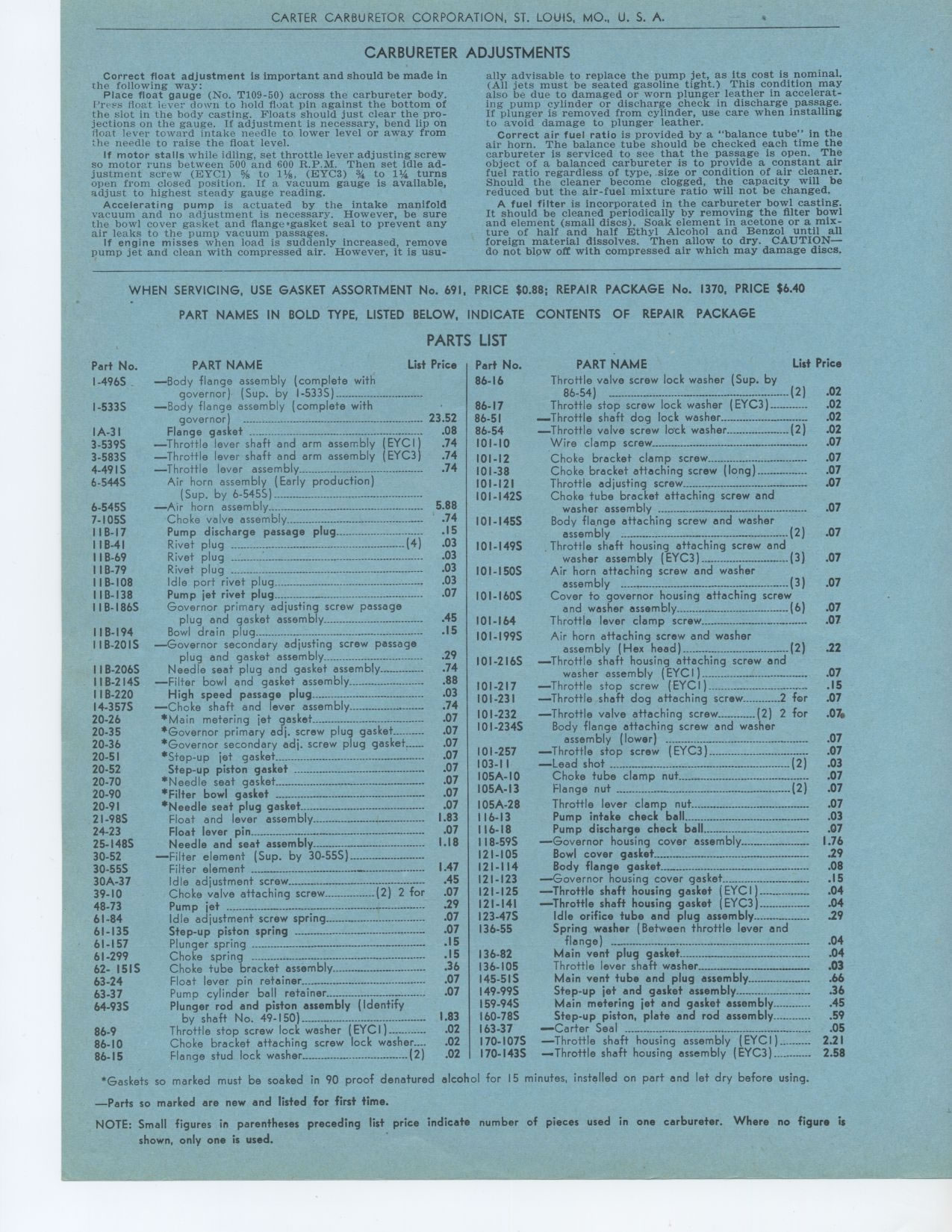
Correct float adjustment is important and should be made in the following way:
Place float gauge (No. T109-50) across the carbureter body. I'rrss float lever
clown to hold float pin against the bottom of the slot in the body casting.
Floats should just clear the projections on the gauge. If adjustment is necessary,
bend lip on float lever toward intake needle to lower level or away from the
needle to raise the float level.
If motor stalls while idling, set throttle lever adjusting screw so motor runs
between 500 and 600 R.P.M. Then set idle adjustment screw (EYC1) % to 11/a,
(EYC3) f to 11/4 turns open from closed position. If a vacuum gauge is available,
adjust to highest steady gauge reading.
Accelerating pump is actuated by the intake manifold vacuum and no adjustment
is necessary. However, be sure the bowl cover gasket and flange •gasket
seal to prevent any air leaks to the pump vacuum passages.
If engine misses when load is suddenly increased, remove pump jet and clean
with compressed air. However, it is usu-
ADJUSTMENTS
ally advisable to replace the pump jet, as its cost is nominal. (All jets must
be seated gasoline tight.) This condition may also be due to damaged or worn
plunger leather in accelerating pump cylinder or discharge check in discharge
passage. If plunger is removed from cylinder, use care when installing to avoid
damage to plunger leather.
Correct air fuel ratio is provided by a "balance tube" in the air
horn. The balance tube should be checked each time the carbureter is serviced
to see that the passage is open. The object of a balanced carbureter is to
provide a constant air fuel ratio regardless of type, size or condition of
air cleaner. Should the cleaner become clogged, the capacity will be reduced
but the air-fuel mixture ratio will not be changed.
A fuel filter is incorporated in the carbureter bowl casting. It should be
cleaned periodically by removing the filter bowl and element (small discs).
Soak element in acetone or a mixture of half and half Ethyl Alcohol and Benzol
until all foreign material dissolves. Then allow to dry. CAUTION-do not blow
off with compressed air which may damage discs.
WHEN SERVICING, USE GASKET ASSORTMENT No. 691, PRICE $0.88; REPAIR PACKAGE
No. 1370, PRICE $6.40
PART NAMES IN BOLD TYPE, LISTED BELOW, INDICATE CONTENTS OF REPAIR PACKAGE
PARTS LIST
Part No. PART NAME List Price Part No.
I-4965 86-16
-Body flange assembly (complete with
governor) (Sup. by I-533S)
I-533S -Body flange assembly (complete with 86-17
governor) 23.52 86-51
IA-31 Flange gasket .08 86-54
3-539S -Throttle lever shaft and arm assembly (EYCI) .74 101-10
3-5835 -Throttle lever shaft and arm assembly (EYC3) .74 101-12
4-49IS -Throttle lever assembly .74 101-38
6-544S Air horn assembly (Early production) 101-121
(Sup. by 6-545S) ° I01-1425
6-545S -Air horn assembly 5.88
7-1055 Choke valve assembly .74 I01-1455
IIB-17 Pump discharge passage plug .15
IIB-41 Rivet plug (4) .03 I01-1495
IIB-69 Rivet plug .03
IIB-79 Rivet plug .03 101-1505
I I B-108 Idle port rivet plug .03
IIB-138 Pump jet rivet plug .07 101-1605
1 I B-1865 Governor primary adjusting screw passage
plug and gasket assembly .45 101-164
IIB-194 Bowl drain .15
plug
IIB-2015 -Governor secondary adjusting screw passage I01-1995
and assembly .29
plug gasket
IIB-2065 Needle seat plug and gasket assembly .74 I01-2165
IIB-214S -Filter bowl and assembly .88
gasket
IIB-220 High speed .03 101-217
passage plug
14-3575 -Choke shaft and lever assembly .74 101-231
20-26 *Main metering jet gasket .07 101-232
20-35 *Governor primary adj. screw plug gasket .07 101-2345
20-36 *Governor secondary adj. screw plug gasket .07
20-51 *Step-up jet gasket .07 101-257
................................................
20-52 Step-up piston gasket .07 103-11
..........................................
20-70 *Needle seat .07 I05A-10
gasket
20-90 *Filter bowl gasket .07 I05A-13
20-91 *Needle seat plug gasket .07 105A-28
21-98S Float and lever assembly 1.83 116-13
24-23 Float lever pin .07 116-18
25-1485 Needle and seat assembly 1.18 118-59S
30-52 -Filter element (Sup. by 30-55S) 121-105
30-55S Filter element 1.47 121-114
30A-37 Idle adjustment screw .45 121-123
39-10 Choke valve attaching screw (2) 2 for .07 121-125
48-73 Pump jet .29 121-141
61-84 Idle adjustment screw spring .07 123.47S
61-135 Step-up piston spring .07 136-55
61-157 Plunger spring ° °-°---- .15
61-299 Choke spring .I5 136-82
62- 15IS Choke tube bracket assembly .36 136-105
63-24 Float lever pin retainer .07 145-51S
63-37 Pump cylinder ball retainer .07 149-99S
64-93S Plunger rod and piston assembly (Identify 159-94S
by shaft No. 49-150) 1.83 I60-78S
86-9 Throttle stop screw lock washer (EYCI) .02 163-37
86-10 Choke bracket attaching screw lock washer .02 170-1075
86-15 Flange stud lock washer (2) .02 170-1435
PART NAME List Price
Throttle valve screw lock washer (Sup. by
86-54) (2) .02
Throttle stop screw lock washer (EYC3) 02
....Throttle shaft dog lock washer 02
-Throttle valve screw lock washer (2) .02
Wire clamp screw 07
Choke bracket clamp screw 07
Choke bracket attaching screw (long) 07
Throttle adjusting screw 07
Choke tube bracket attaching screw and
washer assembly 07
Body flange attaching screw and washer
assembly (2) .07
Throttle shaft housing attaching screw and
washer assembly (EYC3) (3) .07
Air horn attaching screw and washer
assembly (3) .07
Cover to governor housing attaching screw
and washer assembly (6) .07
Throttle lever clamp screw 07
Air horn attaching screw and washer
assembly (Hex head) (2) .22
-Throttle shaft housing attaching screw and
washer assembly (EYCI) 07
-Throttle stop screw (EYCI) 15
-Throttle shaft dog attaching screw 2 for .07
-Throttle valve attaching screw (2) 2 for .07.
Body flange attaching screw and washer
assembly (lower) 07
-Throttle stop screw (EYC3) 07
-Lead shot ...-°-°....° (2) .03
Choke tube clamp nut 07
Flange nut (2) .07
Throttle lever clamp nut 07
Pump intake check ball 03
Pump discharge check ball 07
-Governor housing cover assembly 1.76
Bowl cover gasket 29
Body flange gasket 08
-Governor housing cover gasket 15
-Throttle shaft housing gasket (EYCI) 04
-Throttle shaft housing gasket (EYC3) 04
Idle orifice tube and plug assembly 29
Spring washer (Between throttle lever and
flange) 04
Main vent plug gasket 04
Throttle lever shaft washer 03
Main vent tube and plug assembly 66
Step-up jet and gasket assembly 36
Main metering jet and gasket assembly 45
Step-up piston, plate and rod assembly 59
-Carter Seal 05
-Throttle shaft housing assembly (EYCI) 2.21
Throttle shaft housing assembly (EYC3) 2.58
*Gaskets so marked must be soaked in 90 proof denatured alcohol for 15 minutes,
installed on part and let dry before using.
-Parts so marked are new and listed for first time.
NOTE: Small figures in parentheses preceding list price indicate number of pieces
used in one carbureter. Where no figure is shown, only one is used.