|
CARTER CARBURETOR CORPORATION, ST. LOUIS, MO., U. S. A.
Form 64686—Canadian
OLDSMOBILE 48IS-5045
January, 1941
Reprinted December, 1944
Carb. Series Serial No.
481S-5045 1941,3500 (Oshawa)
135-0001 and higher
4815-5045 1941, 3500 (Regina)
13-80001 and higher
481S-504S 1941, 3600 (Oshawa)
136-0001 and higher
48IS 1942, 3500 235-90004 and higher
4815 1942,3600 236-90004 and higher
504S 1942, 3500 235-00001 to 235-00377
504S 1942,3600 236-00001 to 235-00213
CARBURETER SPECIFICATIONS
For Oldsmobile Six Cylinder Engine, Models "F," "G" and "H"—31/2
Inch Bore, 41/8 Inch Stroke
SERIAL NUMBERS
OLDSMOBILE
3500, 3 600
SERIES
1941-42
No. 4815 used on cars with Hydra-Matic transmission only; 504S used on cars with
Syncro-Mesh transmission only. No. 5045 superseded by 48IS.
Casting No. 340 on Face of Flange
WA- I Down-Draft Carbureters 48IS-504S With Climatic Control—List Price
$29.40
A $6.25 exchange allowance is deducted from the list price if buyer turns in
old carbureter.
Dimensions: Flange size, 11/2 inch S. A. E.
Primary venturi, 11/32 inch I. D.
Secondary venturi, II/16 inch I. D. Main venturi, 13/8 inch I. D.
Float Level: Distance from seam of float (at free end) to tip on lower edge of
float chamber cover, when needle is seated, to be 1/2 inch.
Vents: Outside, No. 10 drill. Inside, none.
Gasoline Intake: Square vertical (push-pull) needle. Size No. 46 drill hole in
needle seat.
Gas Line Connection: 5/16 inch Weatherhead nipple.
Low Speed Jet Tube: Jet size, No. 70 drill. By-pass, size No. 53 drill.
Economizer, .063-.064 inch diameter. Idle bleed, size No. 52 drill.
Idle Port: Length, .190 inch. Width, .040 inch.
Idle Port Opening: .136 to .140 inch above valve with valve closed tight.
Idle Screw Seat: No. 46 drill.
Set Idle Adjustment Screw: 1/2 to 11/2 turns open. For richer mixture, turn screw
out. Do not attempt to idle engine below 6 m. p. h.
Main Nozzle (Assembly): Slip Nozzle, flush type (angle tip)
seats in primary venturi, at 45° angle. Discharge jet size.
.110 inch diameter. Inner nozzle (seats in slip nozzle). I. D.
No. 31 drill.
Nozzle Retainer Plug: Size, No. 30 drill.
Venturi To Nozzle Relation: .305 inch plus or minus .0075 inch. Metering Rod
(Vacumeter Type): Economy step, .07625 inch diameter. Second step tapers to .0715
inch diameter. Third step tapers to .067 inch diameter. Power step, .053 inch
diameter. Length 3-9/64 inches.
Metering Rod Jet: .1015 inch diameter.
Metering Rod Setting: Use gauge, part No. T109-102 (2.468 inches).
Accelerating Pump: Low pressure type with adjustable stroke. Pump discharge jet,
size No. 72 drill.
Relief passage (to outside), size No. 42 drill.
Intake ball check size, No. 60 drill.
Discharge boll check size, No. 32 drill.
Pump Adjustment: 16/64 inch plunger travel (full throttle positice) medium stroke.
Use gauge No. T109-117S.
Choke: Carter Climatic Control, set at index. Butterfly type. offset valve. Choke
heat suction hole, in body, size No. 30 (.128") drill.
Vacuum Spark Port: .039-.041 inch diameter. Bottom of port .030-.035 inch above
valve.
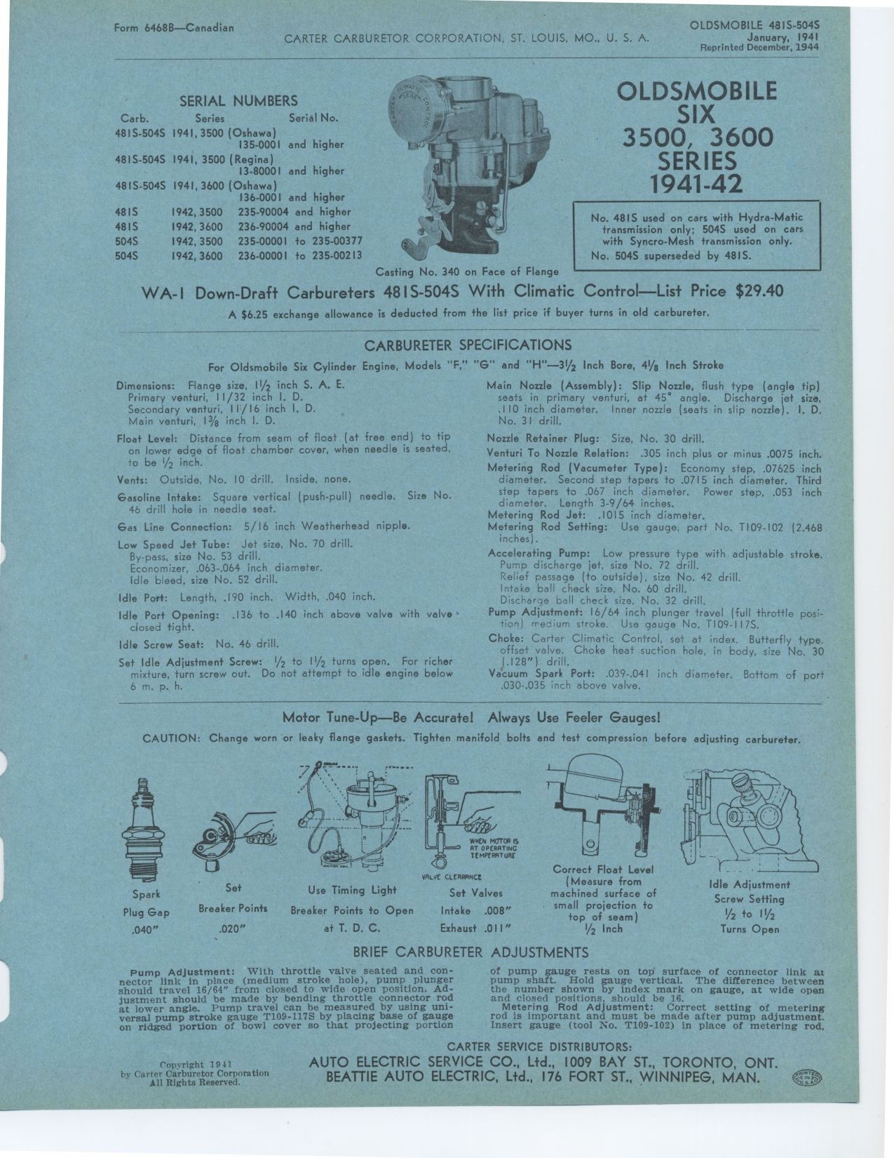
Motor Tune-Up—Be Accurate! Always Use Feeler Gauges!
CAUTION: Change worn or leaky flange gaskets. Tighten manifold bolts and test
compression before adjusting carbureter.
BRIEF CARBURETER ADJUSTMENTS
s_-
Use Timing Light
Breaker Points to Open
at T. D. C.
VALV( CLCRPRNCt
Set Valves Intake .008" Exhaust .011"
Spark Plug Gap .040"
Set
Breaker Points
.020"
Correct Float Level
(Measure from
machined surface of
small projection to
top of seam)
1/2 Inch
r_-
Idle Adjustment Screw Setting
1h to 11h
Turns Open
Pump Adjustment: With throttle valve seated and connector link in place (medium
stroke hole), pump plunger should travel 16/64" from closed to wide open
position. Adjustment should be made by bending throttle connector rod at lower
angle. Pump travel can he measured by using universal pump stroke gauge T109-117S
by placing base of gauge on ridged portion of bowl cover so that projecting portionof
pump gauge rests on top surface of connector link at pump shaft. Hold gauge vertical.
The difference between the number shown by index mark on gauge, at wide open
and closed positions, should be 16.
Metering Rod Adjustment: Correct setting of metering rod is important and must
be made after pump adjustment. Insert gauge (tool No. T109-102) in place of metering
rod,
Copyright 1941
|