|
Form 6566— Canadian PACKARD 643S-643SA-644S
CARTER CARBURETOR CORPORATION, ST. LOUIS, MO., U. S. A. February, 1948
MOTOR SERIAL NUMBERS
643S-SA—G-400015 and higher 6445—G-200015 and higher
PACKARD
SUPER EIGHT
MODELS 2202 2222 2232
STANDARD EIGHT
CAR SERIAL NUMBERS MODELS 2201 2211
643S-SA—2272-I and higher 1948
644S—2262- I and higher (643S Superseded by 643SA)
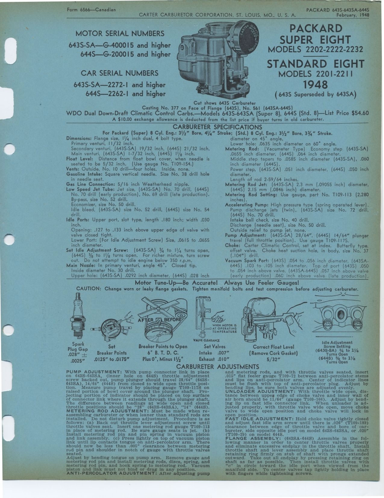
Cut shows 643S Carbureter
Casting No. 377 on Face of Flange (643S), No. 561 (643SA-644S)
WDO Dual Down-Draft Climatic Control Carbs.—Models 643S-643SA (Super
8), 644S (Std. 8)—List Price $54.60
A $10.00 exchange allowance is deducted from the list price if buyer turns
in old carbureter.
CARBURETER SPECIFICATIONS
For Packard (Super) 8 Cyl. Eng.: 31/2" Bore, 414" Stroke; (Std.)
8 Cyl. Eng.: 31/2" Bore, 33/4" Stroke.
Dimensions: Flange size, 11/4 inch dual, 4 bolt type. diameter on 45° angle.
Primary venturi, 11/32 inch. Lower hole: .0635 inch diameter on 60° angle.
Secondary venturi, (6435-SA) 19/32 inch, (644S) 21/32 inch. Metering Rod:
(Vacumeter Type) Economy step (643S-SA)
Main venturi, (643S-SA) 1-7/32 inch, (644S) 11/8 inch. .0655 inch diameter,
(6445) .064 inch diameter.
Float Level: Distance from float bowl cover, when needle is Middle step
tapers to .0585 inch diameter (6435-SA), .060
seated to be 5/32 inch. (Use gauge No. T109-154.) inch diameter (6445).
Vents: Outside, No. 10 drill—four holes. Inside, none. Power step,
(643S-SA) .051 inch diameter, (644S) .050 inch
Gasoline Intake: Square vertical needle. Size No. 38 drill hole diameter.
in needle seat. Length of rod 2-59/64 inches.
Gas Line Connection: 5/16 inch Weatherhead nipple. Metering Rod Jet: (6435-SA)
2.3 mm (.09055 inch) diameter,
Low Speed Jet Tube: Jet size, (6435-SA) No. 70 drill, (644S) (644S) 2.15
mm (.0846 inch) diameter.
No. 70 drill (early production), No. 69 drill (late production). Metering
Rod Setting: Use gauge, part No. TI09-113 (2.280
By-pass, size No. 52 drill. inches).
Economizer, size No. 50 drill. Accelerating Pump: High pressure type (spring
operated lever).
Idle bleed, (6435-SA) size No. 52 drill, (6445) size No. 54 Pump discharge
jets (twin), (643S-SA) size No. 72 drill,
drill. (644S) No. 70 drill.
Idle Ports: Upper port, slot type, length .180 inch; width .030 Intake
ball check, size No. 40 drill.
inch. Discharge (needle seat), size No. 50 drill.
Opening: .127 to .133 inch above upper edge of valve with Outside relief
to pump jet, none.
valve closed tight. Pump Adjustment: (643S-SA) 28/64", (6445) 14/64" plunger
Lower Port: (For Idle Adjustment Screw) Size, .0615 to .0655 travel (full
throttle position). Use gauge T109-I17S.
inch diameter. Choke: Carter Climatic Control, set at index. Butterfly
type,
Set Idle Adjustment Screw: (643S-SA) 3/4 to 11/4 turns open, offset valve.
Choke heat suction hole, in body, size No. 37
(6445) 5/8 to 11/8 turns open. For richer mixture, turn screw (.104")
drill.
out. Do not attempt to idle engine below 350 r.p.m. Vacuum Spark Port:
(643S) .054 to .056 inch diameter, (643SA-
Main Nozzle: In primary venturi, angle 45°. Closed tip. 6445) .103
to .105 inch diameter. Top of port (643S) .050
Inside diameter No. 30 drill. to .054 inch above valve, (643SA-644S) .057
inch above valve
Upper hole: (643S-SA) .0292 inch diameter, (6445) .028 inch (early production)
.06G' inch above valve (late production).
Motor Tune-Up--Be Accurate! Always Use Feeler Gauges!
CAUTION: Change worn or leaky flange gaskets. Tighten manifold bolts and
test compression before adjusting carbureter.
Breaker Points to Open
6° B. T. D. C.
Plus 0°, Minus 11/2°
Spark Plug Gap .028" +
.0025"
Set
Breaker Points
.0125" to .0175"
VALVE CLEARANCE
Set Valves Intake .007" Exhaust .010"
Correct Float Level
(Remove Cork Gasket)
5/32"
Idle Adjustment
Screw Setting
(643S-SA) % to 11/4
Turns Open
(644S) 5/8 to 11/8
Turns Open
CARBURETER
PUMP ADJUSTMENT: With pump connector link in place on 643S-643SA, (inner
hole on 644S) throttle adjustment screw backed out, pump plunger should
travel 28/64" (643S-643SA), 14/64" (644S) from closed to wide open throttle
position. Measure pump travel by placing gauge T109-117S on raised portion
of bowl cover around the plunger shaft. Projecting portion of indicator should
be placed on top surface of connector link where it extends through the plunger
shaft. The difference between readings at wide open and closed throttle positions
should be "28" (643S-643SA), "14" (644S). METERING ROD
ADJUSTMENT: Must be made when re-assembling carbureter or when leaner than
standard rods are installed. Do not disturb pump adjustment. Procedure is
as follows: (a) Back out throttle lever adjustment screw until throttle valves
seat. Insert one metering rod gauge T109-113 in place of metering rod. Be
sure gauge seats in jet. (b) Install metering rod pin and pin spring in vacuum
piston and link assembly. (c) Press lightly on top of vacuum piston link
until lip contacts tongue on anti-percolator arm. There should now be less
than .005" clearance between metering rud pin and shoulder in notch
of gauge with throttle valves seated.
Adjust by bending tongue on pump arm. Remove gauge and metering rod pin
and install metering rods, discs, spring, and metering rod pin, and hook
spring to metering rod. Vacuum piston and link must not bind or drag in
any position.
NTI- PERCOLATOR ADJUSTMENT: After adjusting pumpADJUSTMENTS
and metering rods, and with throttle valves seated, insert .015" flat
feeler gauge T109-72 between anti-percolator stems and lips on anti-percolator
arm. Center of indicator lines must be flush with top of anti-percolator
plug. Adjust by bending lips, be sure both valves are adjusted evenly.
UNLOADER ADJUSTMENT: With throttle wide open, distance between upper
edge of choke valve and inner wall of air horn should be 11/64" (gauge
T109-166). Adjust by bending lip on fast idle connector link. When unloader
is adjusted properly, with throttle valve wide open, move choke valve
to wide open position and choke valve will lock in open position.
FAST IDLE ADJUSTMENT: Hold choke valve tightly closed and adjust fast
idle arm screw until there is .026" (T109-189) clearance between edge of
throttle valve and bore of carbureter, side opposite idle port on model 643S
-643SA, or .020" (T109-29) on model 644S.
FLANGE ASSEMBLY: (643SA -644S) Assemble in the following manner in order
to center throttle valves properly and eliminate excessive endplay in
the throttle shaft. Install throttle shaft and lever assembly and place
throttle shaft retaining ring firmly on stub of shaft with prongs extended
outward. Take out all endplay by pressing retaining ring on shaft as
far as possible. Then install throttle valves with "c" in circle
toward the idle port when viewed from the manifold side. To center valves
tap lightly holding in place with fingers while tightening screws.
|