|
CARTER CARBURETOR CORPORATION, ST. LOUIS, MO., U. S. A.
Form 6461 B—Canadian
PACKARD 478S
December, 1940
Reprinted May, 1945
CAR SERIAL NUMBERS
2001 and higher
MOTOR SERIAL NUMBERS
300051 and higher
PACKARD EIGHT MODEL "120" 1941
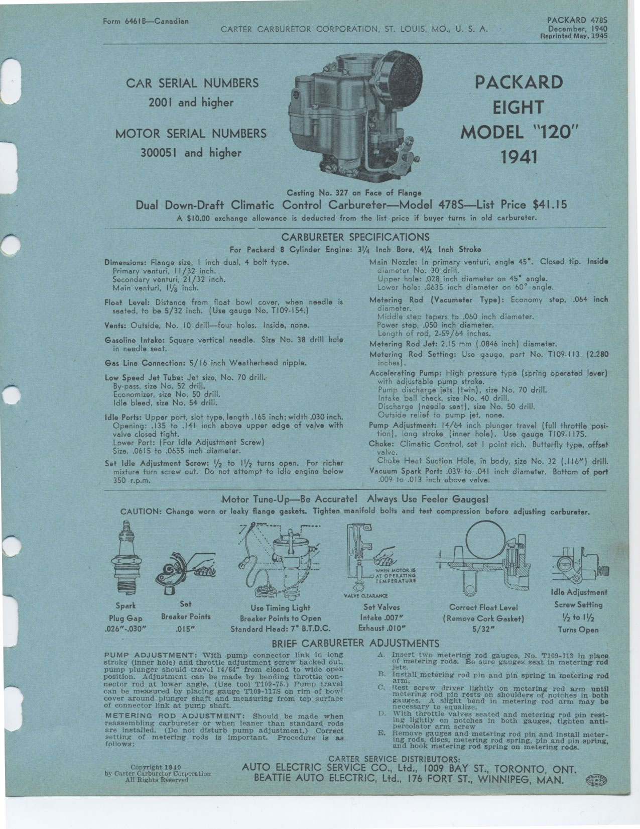
Casting No. 327 on Face of Flange
Dual Down-Draft Climatic Control Carbureter—Model 478S—List Price
$41.15
A $10.00 exchange allowance is deducted from the list price if buyer turns
in old carbureter.
CARBURETER SPECIFICATIONS
For Packard 8 Cylinder Engine:
Dimensions: Flange size, I inch dual, 4 bolt type. Primary venturi, 11/32
inch.
Secondary venturi, 21/32 inch.
Main venturi, 11/8 inch.
Float Level: Distance from float bowl cover, when needle is seated, to be
5/32 inch. (Use gauge No. T109-154.)
Vents: Outside, No. 10 drill—four holes. Inside, none.
Gasoline Intake: Square vertical needle. Size No. 38 drill hole in needle
seat.
Gas Line Connection: 5/ 16 inch Weatherhead nipple.
Low Speed Jet Tube: Jet size, No. 70 drill. By-pass, size No. 52 drill.
Economizer, size No. 50 drill.
Idle bleed, size No. 54 drill.
Idle Ports: Upper port, slot type, length .165 inch; width .030 inch. Opening:
.135 to .141 inch above upper edge of valve with valve closed tight.
Lower Port: (For Idle Adjustment Screw)
Size, .0615 to .0655 inch diameter.
Set Idle Adjustment Screw: 1/2 to 11/2 turns open. For richer mixture turn
screw out. Do not attempt to idle engine below 350 r.p.m.
3¼ Inch Bore, 41/4 Inch Stroke
Main Nozzle: In primary venturi, angle 45°. Closed tip. Inside diameter
No. 30 drill.
Upper hole: .028 inch diameter on 45° angle.
Lower hole: .0635 inch diameter on 60° angle.
Metering Rod (Vacumeter Type): Economy step, .064 inch diameter.
Middle step tapers to .060 inch diameter.
Power step, .050 inch diameter.
Length of rod, 2-59/64 inches.
Metering Rod Jet: 2.15 mm (.0846 inch) diameter.
Metering Rod Setting: Use gauge, part No. T109-113 (2.280 inches).
Accelerating Pump: High pressure type (spring operated lever) with adjustable
pump stroke.
Pump discharge jets (twin), size No. 70 drill.
Intake ball check, size No. 40 drill.
Discharge (needle seat), size No. 50 drill.
Outside relief to pump jet, none.
Pump Adjustment: 14/64 inch plunger travel (full throttle position), long
stroke (inner hole). Use gauge TI09-117S.
Choke: Climatic Control, set I point rich. Butterfly type, offset valve.
Choke Heat Suction Hole, in body, size No. 32 (.116") drill. Vacuum
Spark Port: .039 to .041 inch diameter. Bottom of port .009 to .013 inch
above valve.
Motor Tune-Up--Be Accurate! Always Use Feeler Gauges!
CAUTION: Change worn or leaky flange gaskets. Tighten manifold bolts and
test compression before adjusting carburetor.
Spark
Plug Gap .026"-.030"
Set
Breaker Points
.015"
Use Timing Light
Breaker Points to Open
Standard Head: 7° B.T.D.C.
VALVE CLEARANCE
Set Valves Intake .007" Exhaust .010"
Correct Float Level
(Remove Cork Gasket)
5/32"
Idle Adjustment
Screw Setting
1/2 to I I/2
Turns Open
BRIEF CARBURETER ADJUSTMENTS
PUMP ADJUSTMENT: With pump connector link in long stroke (inner hole) and
throttle adjustment screw backed out, pump plunger should travel 14/64" from
closed to wide open position. Adjustment can be made by bending throttle
connector rod at lower angle. (Use tool T109-75.) Pump travel can be measured
by placing gauge T109-117S on rim of bowl cover around plunger shaft and
measuring from top surface of connector link at pump shaft.
METERING ROD ADJUSTMENT: Should be made when reassembling carbureter or when
leaner than standard rods are installed. (Do not disturb pump adjustment.)
Correct setting of metering rods is important. Procedure is as follows:
Copyright 1940
by Carter Carburetor Corporation
All Rights Reserved
A. Insert two metering rod gauges, No. T109-113 in place of metering rods.
Be sure gauges seat in metering rod jets.
B. Install metering rod pin and pin spring in metering rod arm.
C. Rest screw driver lightly on metering rod arm until metering rod pin rests
on shoulders of notches in both gauges. A slight bend in metering rod arm
may be necessary to equalize.
D. With throttle valves seated and metering rod pin resting lightly on notches
in both gauges, tighten anti-percolator arm screw
E. Remove gauges and metering rod pin and install metering rods, discs, metering
rod spring, pin and pin spring. and hook metering rod spring on metering
rods.
|