|
Form 6245B—Canadian
CARTER CARBURETOR CORPORATION, ST. LOUIS, MO., U. S. A.
PACKARD 366S FEBRUARY, 1937 Reprinted March, 1945
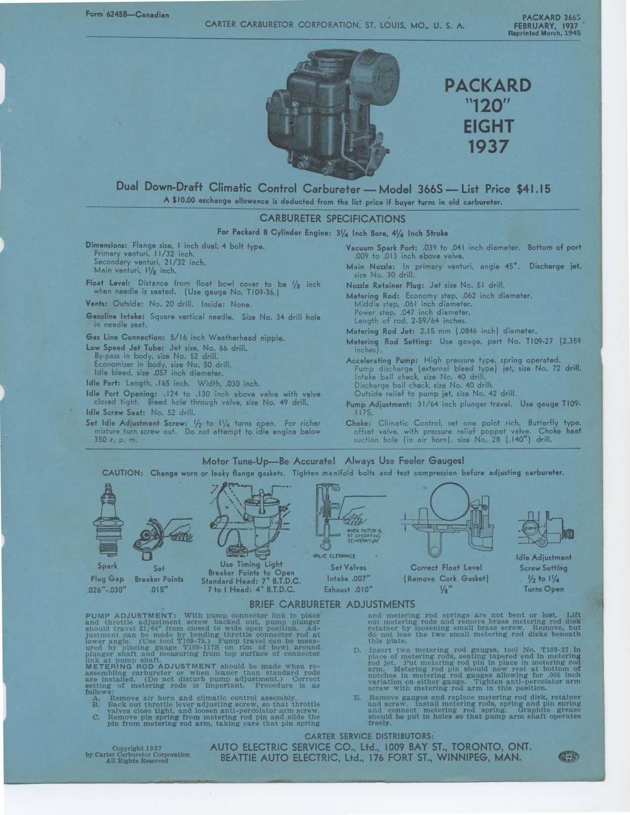
PACKARD "120" EIGHT 1937
Dual Down-Draft Climatic Control Carbureter — Model 366S — List
Price $41.15
A $10.00 exchange allowance is deducted from the list price if buyer turns
in old carbureter.
CARBURETER SPECIFICATIONS
For Packard 8 Cylinder Engine:
Dimensions: Flange size, I inch dual, 4 bolt type. Primary venturi, 11/32
inch.
Secondary venturi, 21/32 inch.
Main venturi, 111/g inch.
Float Level: Distance from float bowl cover to be 1/8 inch when needle is
seated. (Use gauge No. T109-36.)
Vents: Outside: No. 20 drill. Inside: None.
Gasoline Intake: Square vertical needle. Size No. 34 drill hole in needle
seat.
Gas Line Connection: 5/16 inch Weatherhead nipple. Low Speed Jet Tube: Jet
size, No. 66 drill.
By-pass in body, size No. 52 drill.
Economizer in body, size No. 50 drill.
Idle bleed, size .057 inch diameter.
Idle Port: Length, .165 inch. Width, .030 inch.
Idle Port Opening: .124 to .130 inch above valve with valve closed tight.
Bleed hole through valve, size No. 49 drill. Idle Screw Seat: No. 52 drill.
Set Idle Adjustment Screw: 1/2 to 11/4 turns open. For richer mixture turn
screw out. Do not attempt to idle engine below 350 r. p. m.
3¼ Inch Bore, 41/4 Inch Stroke
Vacuum Spark Port: .039 to .041 inch diameter. Bottom of port .009 to .013
inch above valve.
Main Nozzle: In primary venturi, angle 45°. Discharge jet. size No. 30
drill.
Nozzle Retainer Plug: Jet size No. 51 drill.
Metering Rod: Economy step, .062 inch diameter.
Middle step, .061 inch diameter.
Power step, .047 inch diameter.
Length of rod, 2-59/64 inches.
Metering Rod Jet: 2.15 mm (.0846 inch) diameter.
Metering Rod Setting: Use gauge, part No. T109-27 (2.359 inches).
Accelerating Pump: High pressure type, spring operated.
Pump discharge (external bleed type) jet, size No. 72 drill. Intake ball
check, size No. 40 drill.
Discharge ball check, size No. 40 drill.
Outside relief to pump jet, size No. 42 drill.
Pump Adjustment: 31/64 inch plunger travel. Use gauge T109-117S.
Choke: Climatic Control, set one point rich. Butterfly type, offset valve,
with pressure relief poppet valve. Choke heat suction hole (in air horn),
size No. 28 (.140") drill.
Motor Tune-Up—Be Accurate! Always Use Feeler Gauges!
CAUTION: Change worn or leaky flange gaskets. Tighten manifold bolts and
test compression before adjusting carbureter.
Idle Adjustment
Screw Setting
1/2 to I I/4
Turns Open
BRIEF CARBURETER ADJUSTMENTS
Spark Set
Plug Gap Breaker Points .026"-.030" .015"
Use Timing Light
Breaker Points to Open
Standard Head: 7° B.T.D.C.
7 to I Head: 4° B.T.D.C.
VALVC CLtSPSNCC
Set Valves Intake .007" Exhaust .010"
Correct Float Level
(Remove Cork Gasket)
1/8"
PUMP ADJUSTMENT: With pump connector link in place and throttle adjustment
screw backed out, pump plunger should travel 31/64" from closed to wide
open position. Adjustment can be made by bending throttle connector rod at
lower angle. (Use tool T109-75.) Pump travel can be measured by placing gauge
T109-117S on rim of bowl around plunger shaft and measuring from top surface
of connector link at pump shaft.
METERING ROD ADJUSTMENT should be made when re-assembling carbureter or when
leaner than standard rods are installed. (Do not disturb pump adjustment.)
Correct setting of metering rods is important. Procedure is as follows:
A. Remove air horn and climatic control assembly.
B. Back out throttle lever adjusting screw, so that throttle
valves close tight, and loosen anti-percolator arm screw.
C. Remove pin spring from metering rod pin and slide the
pin from metering rod arm, taking care that pin springand metering rod springs
are not bent or lost. Lift out metering rods and remove brass metering rod
disk retainer by loosening small brass screw. Remove, but do not lose the
two small metering rod disks beneath this plate.
D. Insert two metering rod gauges, tool No. T109-27 in place of metering
rods, seating tapered end in metering rod jet. Put metering rod pin in place
in metering rod arm. Metering rod pin should now rest at bottom of notches
in metering rod gauges allowing for .005 inch variation on either gauge.
Tighten anti-percolator arm screw with metering rod arm in this position.
E. Remove gauges and replace metering rod disk, retainer and screw. Install
metering rods, spring and pin spring and connect metering rod spring. Graphite
grease should be put in holes so that pump arm shaft operates freely.
Copyright 1937
|