|
CARTER CARBURETOR CORPORATION, ST. LOUIS, MO., U. S. A.
Form 6240A—Canadian
STUDEBAKER, 37IS
February, 1937
Reprinted December, 1940
MOTOR SERIAL NUMBERS
D-143675
and higher
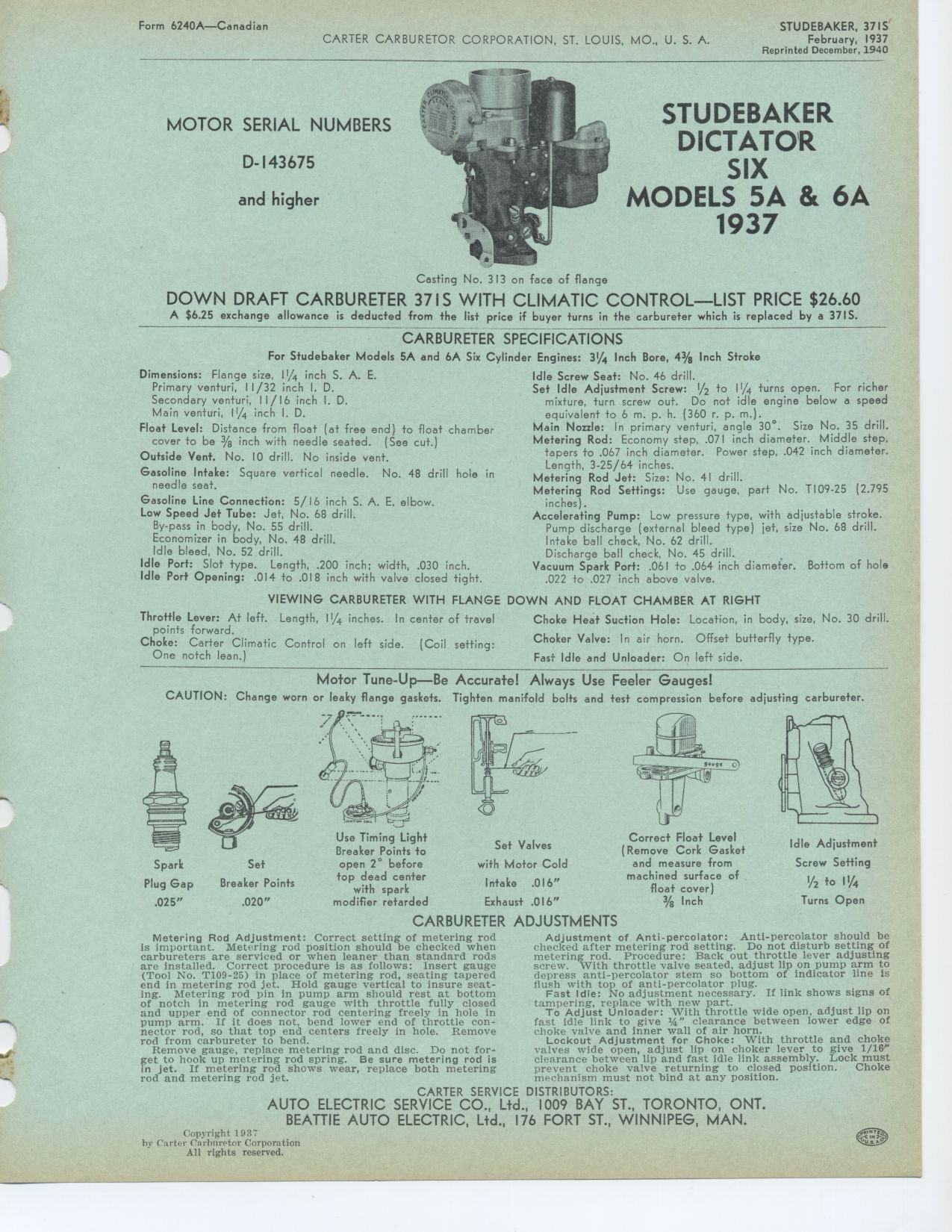
STUDEBAKER DICTATOR SIX MODELS 5A & 6A 1937
Casting No. 313 on face of flange
DOWN DRAFT CARBURETER 37IS WITH CLIMATIC CONTROL—LIST PRICE $26.60
A $6.25 exchange allowance is deducted from the list price if buyer turns
in the carbureter which is replaced by a 37IS.
CARBURETER SPECIFICATIONS
For Studebaker Models 5A and 6A Six Cylinder Engines: 3¼ Inch Bore,
43/s Inch Stroke
Dimensions: Flange size, 11/4 inch S. A. E. Primary venturi, 11/32 inch I.
D.
Secondary venturi, 11/16 inch I. D. Main venturi, 11/4 inch I. D.
Float Level: Distance from float (at free end) to float chamber cover to
be 3/8 inch with needle seated. (See cut.) Outside Vent. No. 10 drill. No
inside vent.
Gasoline Intake: Square vertical needle. No. 48 drill hole in needle seat.
Gasoline Line Connection: 5/ 16 inch S. A. E. elbow. Low Speed Jet Tube:
Jet, No. 68 drill.
By-pass in body, No. 55 drill.
Economizer in body, No. 48 drill.
Idle bleed, No. 52 drill.
Idle Port: Slot type. Length, .200 inch; width, .030 inch. Idle Port Opening:
.014 to .018 inch with valve closed tight.
Idle Screw Seat: No. 46 drill.
Set Idle Adjustment Screw: 1/2 to 11/4 turns open. For richer mixture, turn
screw out. Do not idle engine below a speed equivalent to 6 m. p. h. (360
r. p. m.).
Main Nozzle: In primary venturi, angle 30°. Size No. 35 drill. Metering
Rod: Economy step, .071 inch diameter. Middle step,
tapers to .067 inch diameter. Power step, .042 inch diameter.
Length, 3-25/64 inches.
Metering Rod Jet: Size: No. 41 drill.
Metering Rod Settings: Use gauge, part No. T109-25 (2.795 inches).
Accelerating Pump: Low pressure type, with adjustable stroke. Pump discharge
(external bleed type) jet, size No. 68 drill. Intake ball check, No. 62 drill.
Discharge ball check, No. 45 drill.
Vacuum Spark Port: .061 to .064 inch diameter. Bottom of hole .022 to .027
inch above valve.
VIEWING CARBURETER WITH FLANGE DOWN AND FLOAT CHAMBER AT RIGHT
Throttle Lever: At left. Length, 11/4 inches. In center of travel points
forward.
Choke: Carter Climatic Control on left side. (Coil setting: One notch lean.)
Choke Heat Suction Hole: Location, in body, size, No. 30 drill. Choker Valve:
In air horn. Offset butterfly type. Fast Idle and Unloader: On left side.
Motor Tune-Up—Be Accurate! Always Use Feeler Gauges!
CAUTION: Change worn or leaky flange gaskets. Tighten manifold bolts and
test compression before adjusting carburefer.
Set Valves with Motor Cold Intake .016" Exhaust .016"
Correct Float Level
(Remove Cork Gasket
and measure from
machined surface of
float cover)
3/g Inch
Idle Adjustment Screw Setting
V2 to 11A
Turns Open
ii
Spark Set
Plug Gap Breaker Points
.025" .020"
Use Timing Light Breaker Points to open 2° before top dead center
with spark
modifier retarded
CARBURETER ADJUSTMENTS
Metering Rod Adjustment: Correct setting of metering rod is important. Metering
rod position should be checked when carburetors are serviced or when leaner
than standard rods are installed. Correct procedure is as follows: Insert
gauge (Tool No. T109-25) in place of metering rod, seating tapered end in
metering rod jet. Hold gauge vertical to insure seating. Metering rod pin
in pump arm should rest at bottom of notch in metering rod gauge with throttle
fully closed and upper end of connector rod centering freely in hole in pump
arm. If it does not, bend lower end of throttle connector rod, so that top
end centers freely in hole. Remove rod from carbureter to bend.
Remove gauge, replace metering rod and disc. Do not for-get to hook up metering
rod spring. Be sure metering rod is in jet. If metering rod shows wear, replace
both metering rod and metering rod jet.
Adjustment of Anti-percolator: Anti-percolator should be checked after metering
rod setting. Do not disturb setting of metering rod. Procedure: Back out
throttle lever adjusting screw. With throttle valve seated, adjust lip on
pump arm to depress anti-percolator stem so bottom of indicator line is flush
with top of anti-percolator plug.
Fast Idle: No adjustment necessary. If link shows signs of tampering, replace
with new part.
To Adjust Unloader: With throttle wide open, adjust lip on fast idle link
to give 1/a" clearance between lower edge of choke valve and inner wall
of air horn.
Lockout Adjustment for Choke: With throttle and choke valves wide open, adjust
lip on choker lever to give 1/16" clearance between lip and fast idle
link assembly. Lock must prevent choke valve returning to closed position.
Choke mechanism must not bind at any position.
|