Stromberg
steady running fuel jet for the accelerating gasoline discharge.
The well consists of a standpipe or tube, at the side of the carburetor
(]Figs. 27, 28), whose upper end leads to a horizontal passage
communicating at one end with the carburetor barrel through a small
No. 58 or No. 60 hole (manifold vacuum orifice), and with the atmosphere
through a large accelerating well bleeder, usually No. 32 to No.
31 drill size. With these sizes, the suction of the engine when
idling will draw up gasoline to stand in the position shown.
Around the tube at its lower end is a chamber, filled from the
float chamber, with large holes leading to atmosphere at its top
so that the gasoline in it usually stands at the float chamber
level.
Out of the side of this chamber, about 5/16" above the float
chamber level, is a nozzle which leads to the small venturi.
Besides being the measuring opening for the accelerating discharge,
it serves to hold in place the small venturi.
As previously stated, when the engine is idling or working at light
load, the fuel stands high in the accelerating well tube.
Any increase in the air strength of the cylinder charge is necessarily
attended by a lowering of suction in the intake manifold, under
which circumstances the level of the fuel column in the accelerating
well tube drops.
If the load on the engine is only slightly increased, as by a small
opening of the throttle, the level in the accelerating well tube
will drop perhaps j ", but if the throttle is opened all the
way, the liquid in the accelerating well tube will promptly drop
to the float chamber level.
Around the tube in the lower accelerating chamber is what is known
as the "baffle sleeve" with a %" hole, through which
whatever gasoline that has been displaced in the accelerating well
tube must rise,passing to a groove in line with the accelerating
discharge jet.
The baffle sleeve has a large and free air opening at its top so
that the accelerating discharge jet can-not suck gasoline, but
whenever the level goes down in the accelerating well tube it rises
through the baffle sleeve to the outer end of the accelerating
discharge jet, which then begins to deliver gasoline according
to the suction of the engine in the small venturi tube.
In this way, the accelerating discharge occurs only when the throttle
is opened or the load on the engine increased, and enriches the
different cylinders almost equally in proportion to the increase
of air charge given them.
As a rule, a greater accelerating supply can be used in winter
than in summer.
The delivery of the accelerating discharge jet can be cut down
by fitting a larger accelerating well bleeder, and increased by
using possibly as small as a No. 36 accelerating well bleeder.
If the accelerating well bleeder is too small when the engine is
idling, gasoline will draw up continuously through the accelerating
well tube, generating a shrill hissing sound, and giving the engine
a very rich idling mixture.
The quantity of accelerating charge can also be controlled by changing
the inside diameter of the accelerating well tube. On some 1" Model "O" carburetors,
a %" inside diameter was used, while on the 11"O" carburetors
used on some eight-cylinder cars, the inside of the accelerating
well tube above the level was enlarged to 7/16".
The rate at which the gasoline is fed is controlled by the accelerating
discharge jet, which is as large as No. 51 on 1%2" carburetors
and as small as No. 58 on the 1" carburetors.
ACCELERATING SUPPLY
RAISED BY HIGH MANIFOLD VACUUM
Fig. 27. The Model "O" accelerating well. BEFORE DIS-
Fig. 28. The Model "O" accelerating well. DURING CHARGE,
AT LIGHT LOAD, -HIGH MANIFOLD VACU- DISCHARGE ON CHANGING TO FULL
LOAD, LOW
CM. VACUUM.
Previous page 1927
Supplement Home Next page 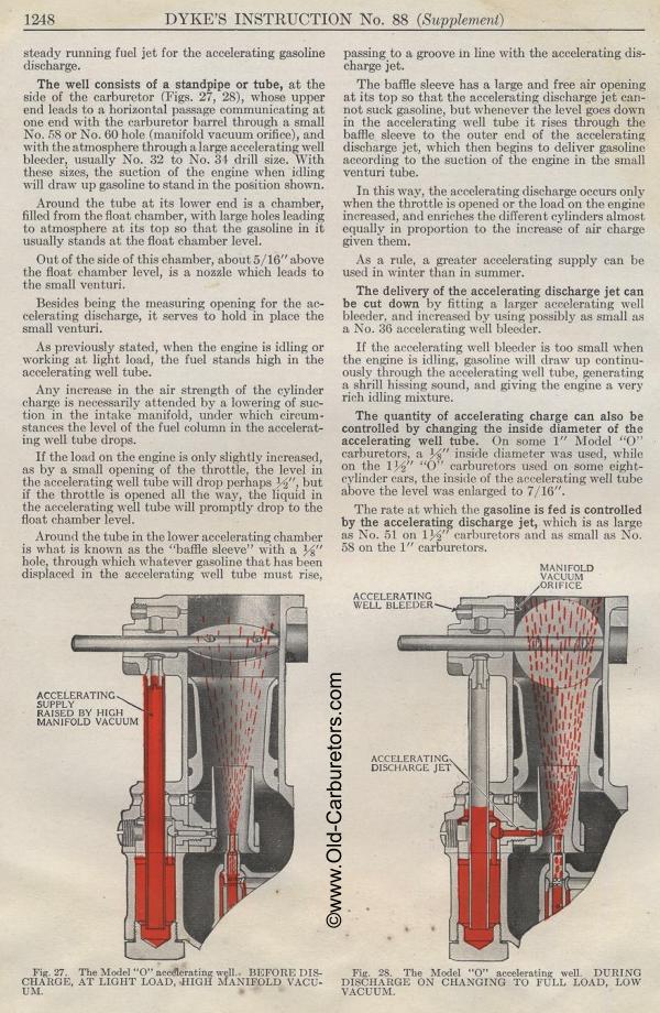
|