THE TYPE "0" SERIES OF HORIZONTAL OR
SIDE OUTLET CARBURETORS
Models and sizes: The horizontal models
of the "O" carburetor
line are the Model "OC," made in the 1)." and 1
%" sizes, and the "OS," made in the 1" and
1 %" sizes.
Both of these models have the double venturi and the air-bleed
economizer action, but the "OC" models have the auxiliary
gasoline control while the "OS" carburetors do not.
The "OS-1" carburetor has the float chamber on the opposite
side of the carburetor barrel from the "OC" and also
has a different location of the idling adjustment, which, instead
of being up near the throttle as in the other "0" carburetors,
is at the top of the idling tube.
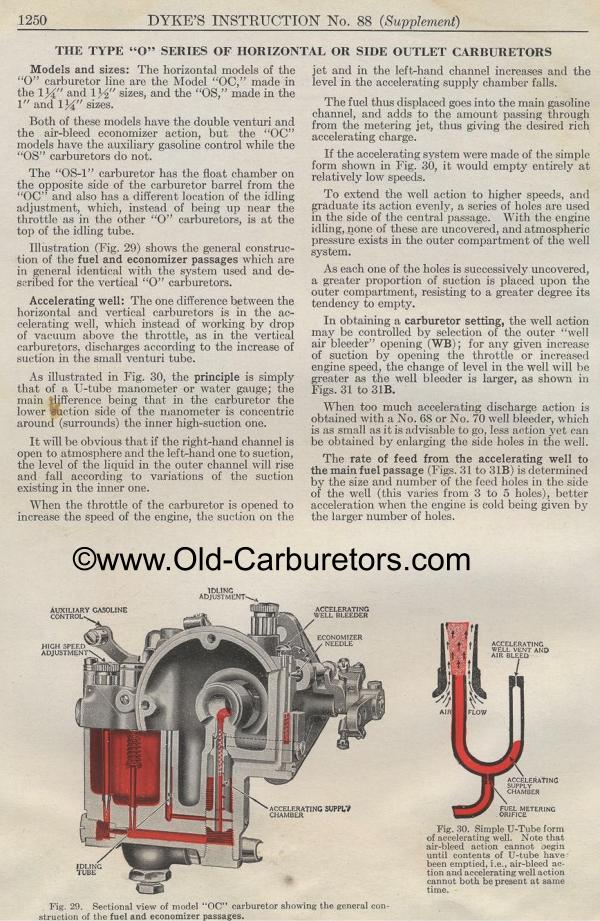
Illustration (Fig. 29) shows the general construction of the fuel
and economizer passages which are in general identical with the
system used and de-scribed for the vertical "0" carburetors.
Accelerating well: The one difference between the horizontal and
vertical carburetors is in the accelerating well, which instead
of working by drop of vacuum above the throttle, as in the vertical
carburetors, discharges according to the increase of suction in
the small venturi tube.
As illustrated in Fig. 30, the principle is simply that of a U-tube
manometer or water gauge; the main difference being that in the
carburetor the lower suction side of the manometer is concentric
around (surrounds) the inner high-suction one.
It will be obvious that if the right-hand channel is open to atmosphere
and the left-hand one to suction, the level of the liquid in the
outer channel will rise and fall according to variations of the
suction existing in the inner one.
When the throttle of the carburetor is opened to increase the speed
of the engine, the suction on thejet and in the left-hand channel
increases and the level in the accelerating supply chamber falls.
The fuel thus displaced goes into the main gasoline channel, and
adds to the amount passing through from the metering jet, thus
giving the desired rich accelerating charge.
If the accelerating system were made of the simple form shown in
Fig. 30, it would empty entirely at relatively low speeds.
To extend the well action to higher speeds, and graduate its action
evenly, a series of holes are used in the side of the central passage.
With the engine idling, none of these are uncovered, and atmospheric
pressure exists in the outer compartment of the well system.
As each one of the holes is successively uncovered, a greater proportion
of suction is placed upon the outer compartment, resisting to a
greater degree its tendency to empty.
In obtaining a carburetor setting, the well action may be controlled
by selection of the outer well air bleeder" opening (WB);
for any given increase of suction by opening the throttle or increased
engine speed, the change of level in the well will be greater as
the well bleeder is larger, as shown in Figs. 31 to 31B.
When too much accelerating discharge action is obtained with a
No. 68 or No. 70 well bleeder, which is as small as it is advisable
to go, less action yet can be obtained by enlarging the side holes
in the well.
The rate of feed from the accelerating well to the main fuel passage
(Figs. 31 to 31B) is determined by the size and number of the feed
holes iii the side of the well (this varies from 3 to 5 holes),
better acceleration when the engine is cold being given by the
larger number of holes.
Fig. 30. Simple U-Tube form of accelerating well. Note that air-bleed
action cannot oegin until contents of U-tube have been emptied,
i.e., air-bleed action and accelerating well action cannot both
be present at same time.
Fig. 29. Sectional view of model "OC" carburetor showing
the general construction of the fuel and economizer passages.
Previous page 1927
Supplement Home Next page 
|
