PIERCE ARROW CARBURETOR AS USED ON SERIES 32 AND 33 CAR
Gasoline system. Air pressure of about 2 1/2 lbs. in the gasoline
tank is maintained by a power-pressure pump on the engine. When
the gauge on dash shows that there is no pressure in the gasoline
system, the hand or emergency pump provides means of obtaining
pressure before the engine is started. The hand-pressure air pump
should have the leather plunger lubricated occasionally with neatsfoot
oil.
Gasoline shut-off cock is located at the top of the gasoline tank,
at the junction of the pipes entering the tank. Turning the valve
either to right or left connects main supply. Should the main supply
become exhausted, turn to valve to opposite side, and a "reserve" of
approximately 5 gallons will be available. To shut off all gasoline
supply turn valve to center position. Tank drain plugs are located
on the under side of tank.
Heating methods: Hot air is drawn from a stove around the exhaust
manifold providing warm air which is drawn into the carburetor
mixing chamber. The point at which it is drawn in is not shown
in the illustration. A cold air regulator with a screen is provided
between the stove and carburetor which call be regulated by hand
to admit more or less cold air.
Hot water is connected from the coiling system to the carburetor
water jacket.
This carburetor as used on the model 32 and 33 cars (with dual
valve engine) is an automatic air valve type, and is similar in
design and operation to the carburetor used on previous passenger
car models.
1. Preliminary Instructions
a) Tighten all nuts which hold the carburetor to the inlet manifold
and the inlet manifold to the engine. There must be no air leakage
between these parts.
b) Remove strainer case (C) and wash off any sediment which may
be on the screen.
c) Remove plug (I) to drain any water or sediment which may collect
in the float chamber.
e) Clean the screens of the cold air regulator on the carburetor
hot-air stove (not shown here; it is underneath the hot air stove
which is connected to exhaust manifold), and adjust according to
the weather.
1. Cold weather — Both screens closed.
2. Warm weather — Rear screen open, front screen closed.
3. Extremely hot weather —Both screens open, or off.
f) Check the height of the gasoline level in the float chamber.
When the car is standing on even ground with the engine not running,
the level should be up to the groove on post (A) (sight glass (AI)
permits inspection). This level is adjusted at the factory, but
if it is necessary to alter it, the best method is to change the
position of the sleeve (B) on the float needle by unsoldering it.
g) Remove the auxiliary air valve screen (D), and clean it, if
necessary. This screen should always he free from dirt. (This screen
(D) is circular in shape and surrounds the three reeds. Air is
drawn in here and (AV) is termed an auxiliary air valve.
Should it be necessary, the auxiliary air valve assembly (AV) can
be removed for inspection and checking by removing the three screws
(F). Wash out any dirt which may be lodged between the reeds (1,
2; third reed not shown) and the case. Check the weight and travel
of the reeds against the following chart.
Reed
Grade Thickness Reed Weight Deflection
No. Travel 14"
53138 Light .012" %" % oz. 1-16"
53137 Intermediate .018" 5-32" 11/2 oz. 1-32"
53136 Heavy .018" 5-32" 2 oz. 1-32"
The total travel is controlled by bending the spring (G). The tension
of each reed is determined by applying the weights (M) to the free
end of each reed through each of the three holes (H) in the case.
A special weight with the proper size stem must be used. See (M,
Fig. 2).
Fig. 2. Auxiliary air valve
AV assembly (round shape) show_ng two of the three reeds (1, 2)
and screen (D) and special weight (M) for testing tension of the
reeds.
The tension of each reed should be such that when the weight (M)
is applied, the reed will open an ammmt exactly equal to that tabulated
under "deflection" in above table. Also, when the reed
is down on its seat, it must have full contact and not permit air
leakage.
When replacing the auxiliary air valve assembly (AV) oil the carburetor,
the light reed (1) should he to the top. A letter (T) is stamped
on the case flange adjacent to the light reed.
2. Preliminary Adjustments
a) Throttle adjusting screw: Retard throttle lever on the steering
column the full amount so as to close the throttle valve (E, Fig.
1).
MAIN
ADJ. T Fro. 1A
Fig. 1. Sectional side view of Pierce Arrow carburetor used on
Series 32, 33 cars. Fig. IA. Top view of carburetor outlet to intake
manifold. (Q) is the high speed adjustment.
by applying air pressure to point (K).
Next loosen lock nut (0, Fig. 3) and back off on screw (P) until
it barely touches the lever (N). d) Remove plug (J) and clean the
idling nozzle Then screw it in again from to 1 turn. Lock
nut (0).
Previous page 1927
Supplement Home Next page 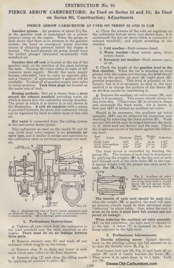
|