Ball & Ball
For low temperatures the primary metering screw (P) having a larger
orifice than that of primary metering screw (B), may he substituted
to (B) to give easier starting and quicker warming-up.
Fuel is metered to the second stage through the metering screw
(H) only when the second-stage throttle blade is open.
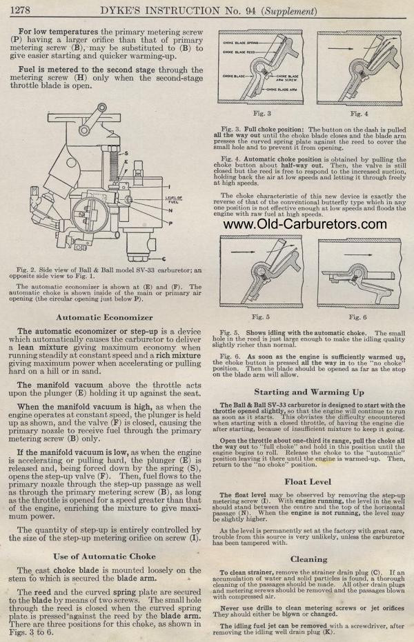
Fig. 2. Side view of Ball & Ball model SV-33 carburetor; an
opposite side view to Fig. 1.
The automatic economizer is shown at (E) and (F). The automatic
choke is shown inside of the main or primary air opening (the circular
opening just below P).
Automatic Economizer
The automatic economizer or step-up is a device which automatically
causes the carburetor to deliver a lean mixture giving maximum
economy when running steadily at constant speed and a rich mixture
giving maximum power when accelerating or pulling hard on a hill
or in sand.
The manifold vacuum above the throttle acts upon the plunger (E)
holding it up against the seat.
When the manifold vacuum is high, as when the engine operates at
constant speed, the plunger is held up as shown, and the valve
(F) is closed, causing the primary nozzle to receive fuel through
the primary metering screw (B) only.
If the manifold vacuum is low, as when the engine is accelerating
or pulling hard, the plunger (E) is released and, being forced
down by the spring (S), opens the step-up valve (F). Then, fuel
flows to the primary nozzle through the step-up passage as well
as through the primary metering screw (B), as long as the throttle
is opened for a speed greater than that of the engine, enriching
the mixture to give maxi-mum power.
The quantity of step-up is entirely controlled by the size of the
step-up metering orifice on screw (I).
Use of Automatic Choke
The cast choke blade is mounted loosely on the stem to which is
secured the blade arm.
The reed and the curved spring plate are secured to the blade by
means of two screws. The small hole through the reed is closed
when the curved spring plate is pressed-against the reed by the
blade arm. There are three positions for this choke, as shown in
Figs. 3 to 6.
Fig. 3 Fig. 4
Fig. 3. Full choke position: The button on the dash is pulled
all the way out until the choke blade closes and the blade arm
presses the curved spring plate against the reed to cover the small
hole and to prevent it from opening.
Fig. 4. Automatic choke position is obtained by pulling the choke
button about half-way out. Then, the valve is still closed but
the reed is free to respond to the increased suction, holding back
the air at low speeds and letting it through freely at high speeds.
The choke characteristic of this new device is exactly the reverse
of that of the conventional butterfly type which in any one position
is not, effective enough at low speeds and floods the engine with
raw fuel at high speeds.
Fig. 5. Shows idling with the automatic choke. The small hole in
the reed is just large enough to make the idling quality slightly
richer than normal.
Fig. 6. As soon as the engine is sufficiently warmed up, the choke
button is pressed all the way in to the "no choke" position.
Then the blade should be opened as far as the stop on the blade
arm will allow.
Starting and Warming Up
The Ball & Ball SV-33 carburetor is designed to start with
the throttle opened slightly, so that the engine will continue
to run as soon as it starts. This obviates the difficulty encountered
when starting with a closed throttle, of having the engine die
after starting, because of insufficient mixture to keep it going.
Open the throttle about one-third its range, pull the choke all
the way out to "full choke" and hold in this position
until the engine begins to roll. Release the choke to the "automatic" position
leaving it there until the engine is warmed-up. Then, return to
the "no choke" position.
Float Level
The float level may be observed by removing the step-up metering
screw (I). With engine running, the level in the well should stand
between the centre and the top of the horizontal passage (N). When
the engine is not running, the level may be slightly higher.
As the level is permanently set at the factory with great care,
trouble from this source is very unlikely, unless the carburetor
has been tampered with.
Cleaning
To clean strainer, remove the strainer drain plug (C). If an accumulation
of water and solid particles is found, a thorough cleaning of the
passages should be made. All other drain plugs and metering screws
should be removed and the passages blown with compressed air.
Never use drills to clean metering screws or jet orifices They
should either be blown or changed.
The idling fuel jet can be removed with a screwdriver, after removing
the idling well drain plug (K).
Previous page 1927
Supplement Home Next page 
|
