CARBURETORS: BALL AND BALL
Cautions
Whenever the engine ceases to perform normally, the carburetor
should be the last thing to look to for trouble. Ninety per cent
of so-called carburetor faults are in reality due to defective
spark plugs, improper valve adjustments, manifold leaks, etc. It
is usually the best plan to check first on all these other factors
before any alteration is made on the carburetor.
A satisfactory idle will not be obtained unless the valves seat
properly and have sufficient clearance. The breaker points must
he clean and the spark plug gaps within .01)2 of .025 inch (some
manufacturers use .031, or ' , claiming this gap is best for idling).
Vacuum-operated devices such as windshield wiper, rectifier, brake
booster, fuel feeder, etc., alter idling conditions; a slightly
rich mixture may be advisable to correct their influence.
To obtain maximum speed and power the linkage must allow full action
of the throttle. Fig. 1 shows in dotted lines how the throttle
lever conies to a stop at (M) when fully opened.
In low temperatures the radiator should be partly covered to allow
the engine to operate at a temperature above 140°F.
Present-day fuels contain heavy fractions which separate from the
more volatile ends and deposit in liquid form on the walls inside
the manifold and are held there by the rush of mixture toward the
cylinders. After the engine is stopped, this heavy fuel drains
down the manifold and for a few minutes drips from the carburetor.
This should not he taken as an indication that the carburetor is
leaking or flooding. The only remedy is a better grade of fuel.
(Manufacturers; Penberthy Injector Co., Detroit, Such.)
BALL & BALL CARBURETOR MODEL "SV-26"
This carburetor is termed a "two-stage, two-quality carburetor.
The following description will explain the principle of operation
of this carburetor and will also serve as the principle for the
model "SV-33."
Fig. 7. Sectional diagrammatic view of the Ball & Ball
model SV-26 and SV-33 carburetor (used on Chrysler "70").
Primary Stage
Air is drawn through the primary air opening (A) and through the
throat (659) and the same vacuum which induces the air flow causes
a flow through the nozzle (Cl), which is in direct communication
with the differential well (D).
Gasoline is drawn from the float chamber through the primary metering
screw (B). At the same time, some air is drawn into the well through
the vents (C2) and (C3).
When the manifold vacuum is high, as at any constant speed on the
primary, the plunger (E) is held up, as shown, and the valve (F)
is closed by its spring, the car is then operating with gasoline
metered through the orifice (B) only.
Opening the throttle further reduces the manifold vacuum, drops
the plunger (E), which opens the valve (F), permitting the additional
or step-up gasoline from the orifice (I) to pass into the primary
nozzle and enrich the mixture.
When the throttle (S65) is in its idling position, the high vacuum
above the throttle draws a mixture of air and gasoline through
the by pass (L4), which has a gasoline metering orifice at (LI).
= This model SV-26 carburetor is similar to the SV-33 de-scribed
on previous pages, with the exception of the second stage bracket.
The explanations referring to either apply to both,
The air-metering orifice (L3) is adjustable by means of the knurled
screw (L) and by screwing this valve in (clockwise) the idling
mixture is made richer and vice versa.
It should be noted here that this idling adjustment is the only
adjustment on this carburetor, as all other metering orifices are
fixed and can be changed only by removing a screw and inserting
another of desired size.
When the engine is operating in such a way that the vacuum above
the throttle (865) is high, as when running on good roads at constant
speed, the plunger (F) is held up, as shown, and a lean mixture
is delivered to the engine as the gasoline is metered by the single
orifice in (B).
When the throttle is opened and the vacuum above the throttle is
reduced the plunger (E) drops, opening the valve (F), and there
is a momentary shot of gasoline followed by a continuous flow of
gasoline and air metered in the right proportion to make the mixture
rich enough for maximum acceleration and power.
This condition continues only until the vacuum above the throttle
increases to the point where the plunger (E) is lifted, when the
lean mixture is again restored.
From this, it will be seen that the economizer functions automatically
at all times and under all conditions to give best economy and
maximum power and is not dependent upon any mechanical means or
any definite position of the throttle.
Second Stage
Illustration, Fig. 7, shows the gasoline metering screw (H), the
throat (869), the second stage nozzle (3027), in its differential
well (J) and the air bleed (657) and the reader will see at once
that, when the second stage throttle (6,53) is opened, these
elements will function, first to give a momentary rich charge
of gasoline and air, followed by a continuous flow of the right
quality for maximum power and acceleration.
The manner of opening the second stage throttle is shown on Fig.
1. The second-stage throttle stem has secured to it the lever (M),
with a roller, and this throttle is held closed by the spring (573).
When the main throttle lever (1006) is opened about 50 degrees
it comes in contact with the roller on (M) and any further opening
of the main throttle opens the second stage throttle rapidly. The
last 25 degrees of opening of the main throttle valve (865) open
the second stage throttle valve (653).
Automatic Choke
The explanation of the automatic choke will serve for this carburetor,
as also will the adjustment instructions, etc., on previous pages.
Previous page 1927
Supplement Home Next page 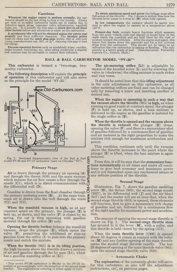
|