Cadillac
It is attached to the left-hand side of the frame under the front
floor boards and is adjusted to release if a pressure of 31—4
pounds should be reached.
As the pump at the front of the engine is designed to furnish a
pressure of considerably less than 32 pounds, it is evident that
the relief valve is not in-tended to release under normal conditions.
The relief valve is intended to operate only in case higher pressures
result from the use of gasoline such as "casing-head" gasoline,
containing highly evaporative fractions.
Fig. 2. Sectional view of air-pressure relief valve.
If the pressure gauge on the instrument board shows a pressure
of more than 4 pounds, the relief valve should be readjusted. Or,
if it is found impossible to maintain sufficient pressure to insure
flow of fuel to the carburetor, this condition may indicate need
for readjustment of the valve.
As low pressure may also be caused by leakage of air at the gasoline
tank filler cap or at the piping connections, or by the presence
of dirt on the needle valve (D) (Fig. 2) or its seat, do not readjust
the relief valve without making certain that the low pressure is
due to the valve releasing and not to these other causes.
To adjust the pressure relief valve, loosen the hexagonal gland
nut (C). Then turn the hollow, slotted screw (B) in the clock-wise
direction if the pressure at which the valve releases is too low;
or in the counter-clockwise direction if the valve releases at
too high a pressure.
Removal: Disconnect the three pipes at the air pressure relief
valve.
Remove the cap screw which holds the relief valve to the side bar
of the frame.
Remove the relief valve.
Disassembly: Remove the cap by turning it counter-clockwise and
pulling it off.
Remove the gland nut (C) and unscrew the screw (B).
Inspection: Examine the needle valve and the valve seat. They should
both be clean and smooth.
The spring should be in good condition. The passages in the body
should be free from dirt. The metal bellows should be free from
holes.
Gasoline Tank Gauge (Electric)
Description: The gasoline tank gauge consists of two elements:
a float unit installed on the tank, and a gauge with a dial on
the instrument boa: J.
The float unit is a variable resistance with a movable contact
that is operated by a float.
One end of the resistance is grounded and the other is connected
to the gauge on the instrument hoard and to the switch, from which
it receives its current supply.
The moving contact, which is also connected to the gauge, divides
the resistance into two parts, the relative sizes of which change
with the level of fuel in the tank.
The gauge on the instrument board is virtually a delicate electrical
instrument for measuring differences in voltage or electrical potential.
It measures the difference between the voltage drop over one part
of the resistance at the float unit and the voltage drop over the
other part.
As the division of the resistance depends upon the position of
the float, the gauge thus indirectly measures the quantity of fuel
in the tank and the dial is accordingly marked to read gallons.
As wired at the factory, the gasoline tank- gauge is connected
to the ignition circuit (the No. 2 terminal on the switch) and
functions only when the ignition is switched on.
When the ignition is switched off, no current flows through the
gauge and it does not then show the contents of the tank. At such
times the gauge hand does not return to zero, but stands somewhere
in the center section of the dial.
The only time the gauge hand stands at zero is when there is current
flowing through the gauge and the tank is empty.
Inspection of connections: It is very important that the terminals
of the float unit be properly connected to the terminals of the
gauge on the instrument board. If, by interchanging the connections
either at the gauge, at the terminal block on the dash, or at the
float unit, the current is allowed to flow from the switch to the
No. 2 terminal on the float unit, the full voltage of the battery
will be short circuited through only one part of resistance. If
the tank ns empty or nearly so, this will result in burning out
the resistance.
Removal of float unit: To remove the float unit, first remove the
two screws that hold the small cap and remove the cap. Disconnect
the two wires. Do not remove the large cap on the gauge.
Remove the four screws that hold the float unit to the tank. Remove
the unit.
Removal of gauge: Disconnect the wires to the gauge and to the
ammeter.
Remove the wing nut on the front side of the instrument pannel
and remove the ammeter and gauge as a unit. The gauge may then
be removed from the ammeter.
Gasoline Tank
Removal: Relieve the tank of all air pressure by removing the filler
cap.
Remove the drain plug and drain the tank.
Disconnect the air and gasoline pipes from the tank by unscrewing
the unions. Disconnect the wires from the float unit.
Remove the cap screw by which the rear of the tank is fastened
to the rear cross member. Remove the nuts on the two bolts by which
the front corners of the tank are attached to the cross member
in front of the tank.
Inspection: With the gasoline tank removed, test it by screwing
on and tightening the filler cap, replacing the drain plug, temporarily
plugging the nipple from which the gasoline pipe was disconnected,
attaching an air hose to the nipple from which the air pipe was
disconnected, and, with the tank immersed in water, turning on
an air pressure of approximately six pounds. Do not use a pressure
greater than six pounds.
Previous page 1927
Supplement Home Next page 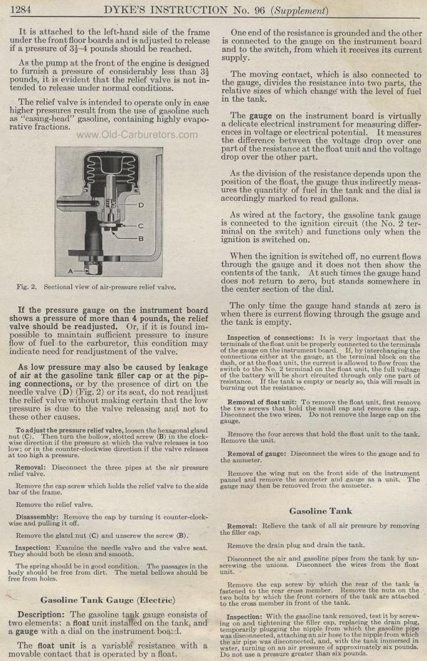
|