LINCOLN CARBURETOR: Construction; Operation This switch is in the circuit between the battery and the heating
or fog-producing element. When the switch is closed the gasoline contained in the retort
is subjected to a temperature above the boiling point of the
fuel, and in a very few seconds the carburetor manifold is filled
with a foggy vapor. The electro-fog generator operates for a period of 10 to 15 seconds, and is then automatically cut off. The first five seconds are required to bring the fuel to the fog point and the remainder of the period to produce sufficient fog for several explosions. Operation: When the carburetor choke control button on the instrument board (connected with 3) is pulled out the first part of the movement of the control closes the carburetor choke valve (7) shutting off nearly all air from entering the carburetor. By pulling the choke control all the way out to the fixed stop
position, one of the members of the electro-fog
switch (2) is
pushed toward and engages the thermostatic member of the switch.
The circuit is thus closed between the battery and the heating
element, which is grounded in the retort. The thermostatic member of the electro-fog switch is composed of two strips of metal (enclosed in electro-fog switch box) having different expansionratios. Closing the circuit causes these strips to become hot and because one metal expands more rapidly than the other the strip bends and after 10 to 15 seconds will break the circuit. The spring strip is operated by a plunger (2) which is actuated
by the lever (4) which- is operated from the carburetor choke
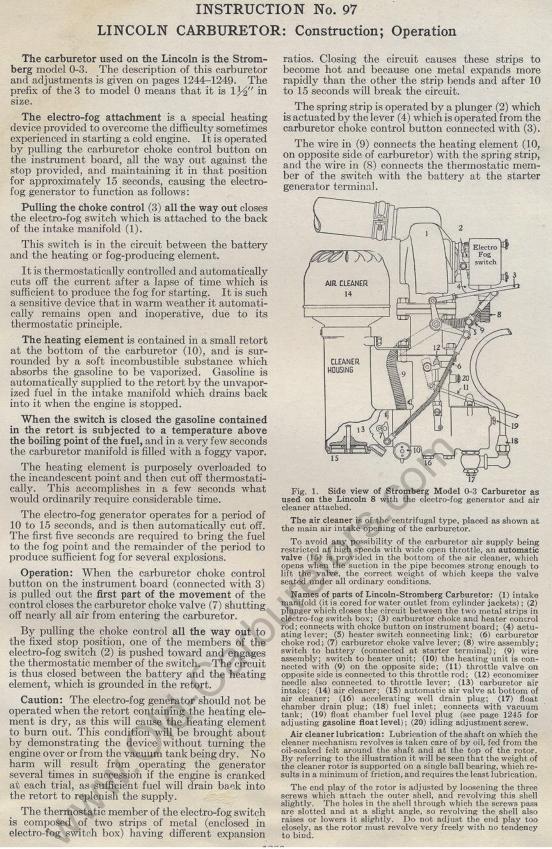
control button connected with (3). The air cleaner is of the centrifugal type, placed as shown at
the main air intake opening of the carburetor. Names of parts of Lincoln-Stromberg Carburetor: (1) intake manifold (it is cored for water outlet from cylinder jackets) ; (2) plunger which closes the circuit between the two metal strips in electro-fog switch box; (3) carburetor choke and heater control rod; connects with choke button on instrument board; (4) actuating lever; (5) heater switch connecting link; (6) carburetor choke rod; (7) carburetor choke valve lever; (8) wire assembly; switch to battery (connected at starter terminal); (9) wire assembly; switch to heater unit; (10) the heating unit is connected with (9) on the opposite side; (11) throttle valve on opposite side is connected to this throttle rod; (12) economizer needle also connected to throttle lever; (13) carburetor air intake; (14) air cleaner; (15) automatic air valve at bottom of air cleaner; (16) accelerating well drain plug; (17) float chamber drain plug; (18) fuel inlet; connects with vacuum tank; (19) float chamber fuel level plug (see page 1245 for adjusting gasoline float level); (20) idling adjustment screw. Air cleaner lubrication: Lubrication of the shaft on which the cleaner mechanism revolves is taken care of by oil, fed from the oil-soaked felt around the shaft and at the top of the rotor. By referring to the illustration it will be seen that the weight of the cleaner rotor is supported on a single ball bearing, which results in a minimum of friction, and requires the least lubrication. Editors Note: Rotor in these old manuals refers to a whole variety of rotating parts; this is even more true in modern days when Ebay, for example, has more than 11,000 auctions for various kinds of rotors. That includes brake rotors. Ignition rotors, motorcycle rotors and many others. The end play of the rotor is adjusted by loosening the three
screws which attach the outer shell, and revolving this shell
slightly. The holes in the shell through which the screws pass
are slotted and at a slight angle, so revolving the shell also
raises or lowers it slightly. Do not adjust the end play too
closely, as the rotor must revolve very freely with no tendency
to bind. Previous page 1927 Supplement Home Next page
|