FORD VAPORIZER;
Construction; Principle of Operation
The vaporizer is a complete assembly of carburetor, intake and
exhaust manifolds, and is now standard equipment on all improved
Ford cars and trucks.
Principle: Water poured on a hot metal surface will immediately
turn into steam and rise in the air. Exactly the same thing happens
when liquid fuel touches the hot-plate in the vaporizer. Vaporization
is caused by automatically bringing liquid fuel to a hot-plate
made of thin sheet steel, which covers a large opening in the exhaust
manifold. This plate is so thin that it becomes very hot as soon
as the engine starts. The top of the hot-plate will have a temperature
of 600 degrees within two minutes after the engine starts.
As soon as the hot-plate turns the liquid into vapor, the vapor
travels up to mixing chamber where it is automatically mixed with
cold air to form a mixture which the spark plug can easily ignite.
Applicable for Ford models of all dates.
Fig. 1. Side view of carburetor, vaporizer, inlet and exhaust manifold
assembly and adjusting and priming-rod assembly.
Fig. 3. Cut-away view of the vaporizer assembly which ex-plains
the principle of operation.
Names of parts on Figs. 1 and 2: (1) exhaust pipe pack nut; (2)
gasoline feed-line nut and packing; (3) elbow: (4) steering-post
throttle lever; (5) throttle rod; (6) throttle lever; (7) throttle-control
rod; (8) clamp screws; (9) gasoline needle-adjusting head; (10)
combined gasoline needle adjustment and choke or priming rod; (11)
gasoline adjusting-rod sleeve; (12) gasoline adjusting-rod head;
(13) collar for choke-wire connection; (14) set screw for collar;
(15) choke wire which connects with (16) and (13); (16) choke lever;
(17) choke lever on end of mixing chamber which connects with front
of radiator with priming wire (18); (18) priming wire to front
of radiator; (19) mixing chamber; (20) hot-plate cover; (21) screws;
(22) union nut, connects with the hot-plate assembly and mixing
chamber; (23) (blank); (24) the thin sheet-metal hot-plate placed
behind cover (20) (all fuel must pass over it; an indentation or
recess is stamped in the plate); (25) base of air tube (B, Fig.
3); (26) throttle stop screw for idle adjusting.
Principle of operation: A suction occurs at opening of inlet manifold
as piston travels down on suction stroke. This suction or vacuum
causes the air and gasoline to be drawn intocylinder, the path
of which is shown by arrows, beginning with A, explained as follows:
Primary air enters at (A) (when starting with choke valve E closed
the air is restricted to only the small opening at R). The air
is heated as i t passes through air tube (B) because it is surrounded
by the main exhaust outlet (G). The air then picks up a charge
of gasoline from the carburetor, carries it over the thin sheet
metal hot-plate (C) which thoroughly vapo-izes the gasoline. The
hot vapor is then carried through passage (D), then picked up by
the secondary cold air current at venturi (V) which enters at air
intake valve (E), and then drawn into the intake manifold (F),
through throttle valve (T) from where it goes to the cylinders.
Names of parts: (A) primary air intake; (B) air tube; (C) hot-plate;
(D) hot gas vapor; (E) choke valve in air intake opening of mixing
chamber; (F) intake manifold; (I) float, copper or brass; (K) gasoline
float needle valve; (L) gasoline feed supply inlet; (M) atmospheric
vent to float chamber; (N) automatic air valve stop screw; (0)
automatic air valve, purpose of which is automatically to control
air supply for rapid acceleration; (R) air passage; (S) drain valve-plug
assembly; (T) butterfly throttle valve; (U) choke lever (17).
See page 1139A for adjustments and advantages of this vaporizer.
See pages 1131, 1132, for Holley model "NII" and page
1130 for Kingston model "L4" carburetors formerly used.
Fig. 2. Front end view of the complete assembly as shown in Fig.
1, including the throttle control.
Previous page 1927
Supplement Home Next page 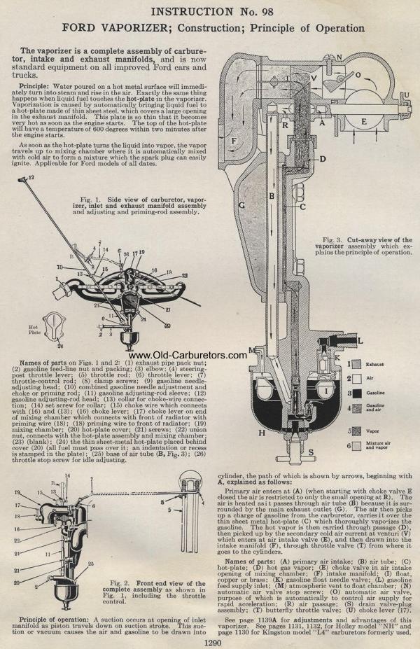
|