CARBURETORS: ZENITH
How the Compensating Jet Acts
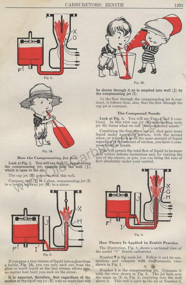
Look at Fig. 2. You will see that (I), representing the compensating
jet, empties into the well (J), which is open to the air.
The cap jet (H) connects with this well.
Compare well (J) to a glass, compensating jet (I) to a bottle,
and cap jet (H) to a straw.
Fig. 2.
If you pour a tiny stream of liquid into a glass from a bottle,
Fig. 2A, you can only suck out from the glass as much liquid as
the tiny stream allows you, no matter how hard you suck on the
straw.
It is apparent, therefore, that regardless of the suction at the
tip of cap jet (H) only as much fuel will
Fig. 2A.
be drawn through it as is emptied into well (J) by the compensating
jet (I).
i`.s the flow through the compensating jet is constant, it follows
then, also, that the flow through the cap jet is constant.
The Compound Nozzle
Look at Fig. 3. You will see Figs. 1 and 2 combined. In this view
cap jet (H) surrounding main jet (G) forms what we call "the
compound nozzle."
Combining the first straw, or jet, that gave more liquid under
increasing suction, with the second straw, or jet, which gives
the same amount of liquid regardless of the amount of suction,
you have a compound feed or nozzle.
This will permit the total flow of liquid to increase only within
definite limitations and, by varying the size of the straws, or
jets, you can bring the rate of flow absolutely under your control.
Fig. 3.
How Theory Is Applied in Zenith Practice
The illustration, Fig. 4, shows a sectional view of the model "U" Zenith
carburetor.
Number 8 is the main jet. Follow it and its connections and compare
with diagrammatic view shown in Fig. 1.
Number 6 is the compensating jct. Compare it with the view shown
in Fig. 2. The jet here acts the same as (I) in Fig. 2, emptying
into the well above it. This well is open to the air at Number
3.
Previous page 1927
Supplement Home Next page 
|
