Zenith
Fig. 5. View showing detail of the idling and starting jet. (See
further explanation on pg. 1295 under "Idling and Starting
Jet.")
Fig. 4. Sectional view of the Zenith model "U" carburetor.
Name of parts: 1, idling jet passage; 2, idling jet; 3, opening
to compensating jet; 4, cap jet; 5, air intake; 6, compensator;
7, compensator jet passage; 8, main jet; 9 (see Fig. 5) idling
tube; R, venturi or choke tube (note there is only one venturi
here, whereas on the model "SV" pages 1297, 1298, there
are two venturi, a small and a large one).
The single venturi carburetor is used considerably on small engines,
requiring in most instances 1" outlets. On larger engines,
requiring 1 %" sizes up, the double venturi carburetor. such
as the model "SV" is used considerably.
Fig. 6. The main jet is shown in black. This receives gasoline
direct from the carburetor bowl, so gives an increasingly rich
mixture as the suction increases.
Fig. 7. The compensating jet is shown in black. The gasoline flowing
through this is limited only by the size hole through it, giving
a constant flow of fuel when the suction —and consequently
the air — is increased.
This means a leaner mixture as the gas suction is increased.
Fig. 8. The compound nozzle (the main and compensating jets) is
shown in black and both are in actual operation, bcth jets supply
gasoline, one growing richer, one leaner, as greater demand is
made on the carburetor by the engine.
By selecting the proper sizes of main and compensating jets for
any given installation, the relation of total gasoline to air drawn
through the carburetor can be kept constant and exactly correct
at all engine speeds.
<
Previous page 1927
Supplement Home Next page 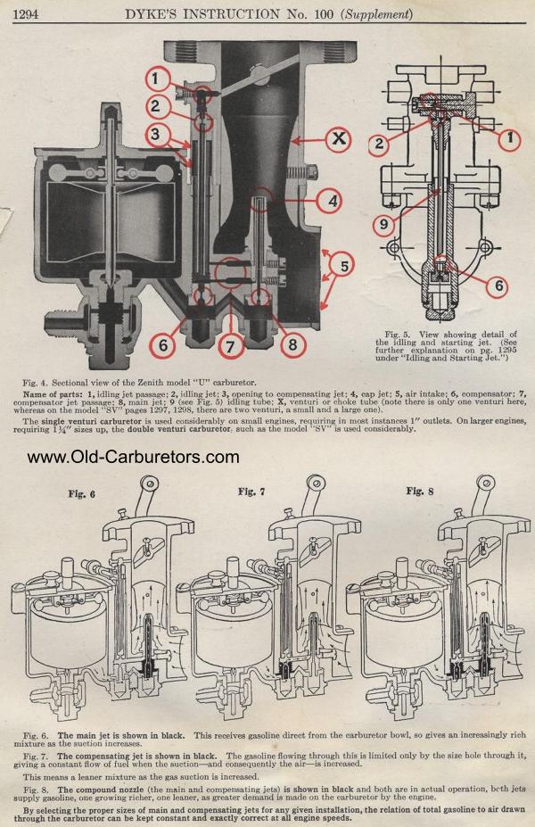
|