SUPERCHARGERS
Types of Superchargers
For all practical purposes in this article it probably is sufficient
to confine ourselves to the Root blower type of supercharger, the
exhaust-driven centrifugal type, and the mechanically driven centrifugal
type.
The exhaust-driven centrifugal type is used chiefly on airplane
engines, where there are better facilities for cooling, because
the turbine or rotor and surrounding parts become intensely hot.
The low density of the air at high altitudes reduces its heat conductivity
and capacity for heat absorption so much that a supercharged engine
which develops the same power at 15,000 or 20,000 feet as it does
at sea level requires more cooling surface than it does when normal
power is developed at sea level.
In addition to being subjected to the heat of the exhaust gasses,
there is also the heat produced from the action of the air compressor.
Coap usrD AIR TO TER
Fig. 1. An exhaust-driven type of supercharger used mostly in aircraft
engines. The exhaust gases drive a. turbine which is directly connected
to a centrifugal air compressor, the delivery pipe of which runs
directly to the carburetor air intake.
The general layout of the exhaust-driven type of super-charger
is shown in Fig. 1.
It is not likely that this type will lend itself to passenger car
application, since the cooling offers a distinct problem as well
as the maintenance of the rotor and other parts sooner or later
affected by the heat. The materials for making the impeller blades
have to be very carefully selected and the proper proportioning
of the vanes or blades is a ticklish job.
The Root blower type of supercharger is shown in Fig. 2. The installation
diagram of the device as used by. Mercedes will give some idea
of its position on the engine.
-------------------
E HOUSING
Fig. 2. Layout of the Root blower type supercharger on the Mercedes.
This is the first stock car to fit such a device and while the
engine is normally rated at 24 h.p. it will develop 100 h.p. with
the supercharger in action, the latter being accomplished by the
blower clutch operating rod when the foot throttle is fully depressed.
In the Mercedes the blower is placed at the front of the engine
and driven from the end of the crank-shaft. The unit is quite compact
and takes in theblower proper, drive gear mechanism and clutch.
The clutch is necessary because the supercharger is not operating
all the time, being brought into action when the foot throttle
is opened all the way. When this happens the blower clutch rod
moves forward and connects the blower with the crank-shaft.
The blades are driven by a pair of gears which mesh with each other,
causing the blades to revolve in opposite directions.
One of the gear spindles has a small bevel pinion attached to it
meshing with a larger bevel gear attached to the clutch.
Fig. 3. Sectional view of the Root blower type supercharger. In
this design the clearances between the blades and between the blades
and housing have to be kept very small. The blades revolve in opposite
directions. The manner of driving the blades as done by Mercedes
is shown at the right.
The air intake of the blower is on the right side of the engine,
while the delivery pipe to carburetor is on the left. As will be
noted, an air cut-off valve is placed in the normal air inlet of
the carburetor and this valve is operated in connection with the
blower clutch operating rod. As the blower is brought into action
the cut-off valve is shut and all the air then is forced through
the carburetor by way of the blower delivery pipe.
Although not shown in the illustration, the delivery pipe from
the blower is made with longitudinal fins for cooling.
The mechanism of the Root blower type of super-charger has to be
very carefully made, especially since the clearance between the
blades and housing has to be kept to within a few thousandths of
an inch. Since the blades and gears revolve at very high speed,
the layout Must be carefully made to keep noise to a minimum.
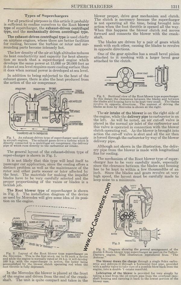
Fig. 3. Diagram showing the general arrangement of the double 8
Roots blower type supercharger as used on the Talbot-Darracq engine.
This illustration reproduced from "The Autocar."
The blower draws the charge through a single Soles carburetor and
delivers it through a horizontal feed pipe, provided with a safety
valve to take care of a possible blow-back from the engine, into
a double iintake manifold.
Lubrication of the blower is provided for very simply by taking
a lead from the oil return pipe from the overhead earn-shaft housing
and carrying it back to the lowest portion of the blower case.
Previous page 1927
Supplement Home Next page 
|