ENGINE BEARINGS
simply removing the old bearing halves and slipping in a new one;
the job is then considered complete.
The interchangeable type main bearing is always of the bronze-backed
or steel-backed babbitt-lined type.
Interchangeable type main bearings are used in the Oldsmobile,
Oakland, Overland 96, Chrysler, Wills-Sainte Claire, Overland Six,
and Marmon cars of 1926 model. The inter-changeable type bearing
can be secured of the Bohn Metal Products Co., Detroit, Mich.,
and Federal-Mogul Corpn., Detroit, Mich., and other bearing manufacturers.
6. Bore, line ream and burning in process. Crankshaft bearings
are line reamed to approximately crankshaft diameter, crankshaft
is then installed and the caps bolted down after which the case
is placed on the burning-in machine and given about one minute
of running, without oil.
This serves to flow the babbitt into conformity. with the crankshaft
shape and leaves a 90 to 100 per cent bearing surface.
The main bearings are then given about 20 minutes of running in,
after which the connecting rods are put through the burning-in
process in the same manner.
Sequence of Operations Method No. 1'
The line reamer and burnishing method is the most popular among
manufacturers at this time. The sequence of operations in using
this process of fitting is as follows:
The crankcase bearing holes or seats are machined to a specified
size, either by boring, flycutting or reaming.
The bearings are installed in the case and cap.
Bearings are filed flush with cap and case, or may be given a slight
protrusion of approximately .002".
If the bearings are of the shimmed or eccentric style, a thick
shim is added on each side to make the inside bore approximately
circular. These shims are usually about 1/32" thick.
Adjusting shims of from .0015" to .00-1" thickness are
added to the thick shins on each side to permit adjustment later
as wear occurs.
The main bearing caps are bolted down.
The first operation of preparing the babbitt surface follows. This
operation may be boring or flycutting.
During the flycutting operation, case is centered by camshaft bearing
holes. The flycutter bar proper is similar to a long boring bar
(Fig. 12 at right). It is about .001" smaller in diameter
than the inside diameter of the bushings.
The bar is fitted with one or more (usually one for each main bearing)
cutters or tool bits which are adjustable by means provided for
moving them out from the center of the bar. Diamond insert tools
are finding favor for use on the flycutter.
GUN GENUS EON MAIN NEARING
Fig. 12. A flycutting bar and a gun type reamer which is also sometimes
used on main bearings for the finishing operations.
The bar is considerably longer than the crankcase, and being just
slightly smaller in diameter than the inside bore of the bushings,
a pilot effect is secured. Some fly-cutter bars are piloted by
special brackets attached to engine crankcase.
1 This is the most widely used factory method.
The bar is set to cut to a diameter about .002" smaller than
the crankshaft diameter, so that enough stock is left for the subsequent
line reaming operation.
Flycutter is run through all bearings, and revolves at a very high
speed with a slow feed. Line reamer is set to about .002" larger
than the crankshaft diameter. A pilot or guide is provided on the
reamer for each bearing to insure alignment. Rotation of the line
reamer is accomplished by hand or by the use of a portable pneumatic
drill, fitted with a suit-able chuck for holding reamer. (Line
reamer is run through all bearings.)
Bearing caps are removed. (A .002" shim is re-moved from under
each cap.) Shaft is laid in case. (A coat of Prussian blue or lamp
black is applied to each main bearing journal.)
One cap is bolted down and crankshaft is rotated a few times by
hand to test for tightness. Fitter removes the cap to observe amount
of contact or "spotting."
Hand scraper used to touch up fillets if they are causing tightness.
(Operation repeated on each main bearing.)
Bearing that takes end thrust of crankshaft is tested for end clearance
with feeler gauge (see Fig. 27). (End clearance tolerances held
to .002 plus or minus.)
Clearance allowed varies on particular engine from minimum of .003
to maximum of .010. .002 shim previously removed is replaced and
crankshaft is bolted down permanently.
One manufacturer makes use of a gun reamer to finish surface on
main bearings (Fig. 12).
Procedure on Connecting Rods
After splitting big end of rod, bearing seats are prepared either
by milling, boring, or fly cutting. (On high-priced jobs, the connecting
rod and cap are internally ground to provide seats for bearings.)
Lining metal is installed by casting into rod, or by using removable
bronze backed bearings.
If bearing halves are shimmed eccentric type compensating shims
are added to bring inside diameter to approximate circularity.
Rod and cap faces are milled or ground to provide good joint between
cap and rod.
With cap bolted to rod, bearings are bored (with boring tool slow
speed) flycut, or broached to semi-finish size.
Bearings are line reamed to specified size and then burnished by
clamping over a revolving mandrel. Bearings tested on oversize
arbor, which gives enough clearance for expansion and oil clearance.
Burnishing2 operation. (Not to be confused with burning-in,' as
the rod is not clamped around the mandrel tight enough to cause
babbitt to flow.)
'Burning-in involves tightening the bearings around their journals
and then rotating the crankshaft by means of a device called a
burning-in machine (see page 787), until sufficient heat is created
to slightly flow the babbitt into conformity with the surface of
the crankshaft main and connecting-rod journals. The burning-in
process is carried on with little or no lubrication between bearing
and journal.
The burnishing-in process is accomplished with a burning-in machine
or other outside source of power to rotate th ,crank-shaft. The
caps are drawn down until there is a drag at each bearing and bearings
are flooded with oil and the crankshaft rotated to produce the
final smooth finish and to limber up the bearing. Burnishing-in
process is used as a final operation after burning-in, and is also
used where the preliminary fitting is by hand scraping, line reaming,
etc.
Previous page 1927
Supplement Home Next page 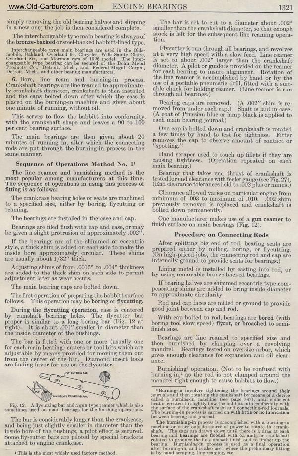
|