ENGINE BEARINGS
If the bearings have not previously been tampered with by some
inexperienced mechanic, it will be found that the split halves
of cap and rod will come together without showing any daylight
at any point. In other words, they will he flat and true on both
sides, as indicated. This check is made with rod and cap tightly
bolted together.
This inspection and those referred to in the two following paragraphs
are described in further detail on page 1317 under the heading "Conditions
other than looseness which may cause excessive oil leakage from
bearings."
In the case of removable-type bearings the split edges of the half
bearings should also come together evenly to form a tight joint
as indicated at Fig. 6 at (D).
If the half bearing split edges are considerably below the surface
of rod and cap split face when assembly is bolted together as shown
at Fig. 6, at (C) it will be advisable to buy new bearings rather
than remove too much metal from cap and rod forging.
It should be remembered that removable bearing split edges should
project from .001" to .0025" above the split face of
cap when the assembly is unbolted as indicated at Fig. 18.
Fig. 18. This method of testing for amount of bearing protrusion
is accomplished by passing two bolts through the
Steel Plate connecting-rod bolt
holes. A steel plate is
- -- placed over the ends of the bolts and with the bearing half
in place, the nuts are tightened on bolts to draw the bearing half
snugly into position on its seat. The amount of protrusion of the
bearing half above
the split edge's then determined by inserting a feeler gauge at point indicated
by arrows. This method is recommended by Federal Mogul Corpn., and can be applied
to both main and connecting-rod bearing halves. (H) is slotted for various bolt
centers.
In case the bearings are only a few thousandths be-low the split face cap forgings,
the correction for pinch can be obtained by lapping down cap on emery cloth laid
over a smooth board or surface plate.
To do this job properly the bearings should be removed from their caps. The caps
are then lapped down, using the mikes to determine amount of metal removed by
checking thickness of cap and also of rod at bolt bosses as shown at Fig. 19.
Never place shims behind bearings to raise them to height and never place shims
between split faces of bearings in order to bring them to height of rod or cap
split face.
If a removable type bearing is surfaced or filed off too much, so as to prevent
upper and lower bearing from sealing together (with bearing cap drawn tight),
it will place an excessive strain on the bearing anchor screws. The added strain
may cause the screws to loosen or break, and the bearing will ruin the shims,
oscillate in the rod, and wear into the cap forging. Excessive oil leakage will
also result and the condition will be noted when the test tank is applied. tinder
this condition a new cap and bearing should be installed.
Three causes of broken bearing caps are: shaft out of round, shaft sprung, and
rod badly bent.
If 70 per cent of the total babbitt surface in rod and cap shows a smooth, gray
surface, it indicates that the contact or spotting is correct, and the mechanic
can proceed to tighten the bearing by removing shims or lapping down the cap
and bushing assembly separately.
Dark brown or black spots on the babbitt surface indicate low areas, which means
that the original fitting of the bearing did not give it a good spotting or contact
surface.
If these points of non-contact cover more than 30 per cent of the surface, it
is advisable to touch up the bearing with a scraper while adjusting so as to
increase the contact area.
If the surface of the babbitt has a considerable number of small holes, or is
in any way roughened, due to being too tight, it should be rescraped by hand
or resurfaced with a reamer before attempting adjustment.
Adjustment of Connecting-Rod Bearings
for Clearance
The clearance between the crankpin and the inside diameter of the connecting-rod
bearings should be .001" for each inch of crankpin diameter, or on an average
about .002" clearance for the ordinary engine.
One of the quickest ways to gauge this clearance is to place the connecting rod
on the crankpin and then insert a piece of .001" or .0015" shim stock,
or, a Ris la Croix cigarette paper folded double, will be about right for this
purpose.
C,aotg:ec orcr00
Now put the connecting-rod cap in place, making sure that the paper or piece
of shim stock lies smoothly on the pin.
Set rod bolt nuts up as tight as possible, and try the rod for tightness on the
pin.
If the proper clearance is present, the rod and piston assembly will hang and
require considerable effort to turn on crankpin. Approximately 10 lbs. pull at
piston end of rod should be required to break loose.
Now take off the cap and remove cigarette paper or shim stock, and then put cap
back and again tighten nuts. If the rod assembly will now turn freely on the
pin and drop of its own weight, it indicates the correct clearance. The rod is
then aligned on a jig, after which it is ready for reinstallation.
Fig. 21. Before lapping bearing halves (B), check th eir height with dial gauge
(G).
Fig. 19. To make sure that an equal amount is removed, check height of cap with
mike.
Fig.20. Diametrical clearance may be deter-mined with a Ris la Croix cigarette
paper, by folding it over once and inserting between rod and cap.
Previous page 1927
Supplement Home Next page 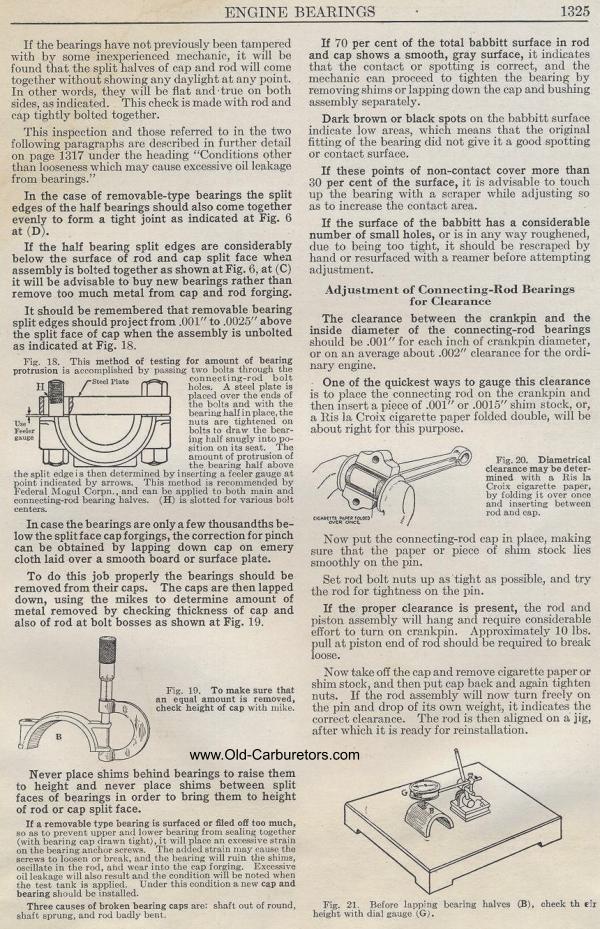
|