Engine Bearings
In making this test on a shimless type of
bearing, if the clearance
is found to be excessive, the bearing. is tightened as follows:
Remove bearing half from connecting rod cap. Mike the thickness
of cap as shown at Fig. 19, and also determine height of bearing
half with dial gauge as shown at Fig. 21.
The cap is now lapped down slightly on emery cloth, and the same
is done to the bearing half. After lapping for about a minute (depending
on amount of looseness), recheck the cap with mikes and the bearing
half with the dial gauge to make sure that same amount of metal
has been removed from the split edges of each. This method will
maintain the original and necessary protrusion of bearing half.
Where the bearings are fitted with shims, this method need not
be followed, as it is only necessary to remove enough shims to
create the 10 lbs. drag, then add a .0015" shim on each side
and bolt up.
It is also advisable to check the amount of side-clearance of the
connecting-rod bearing on its crankpin at the time of adjustment
and renewal. There are no universal standards that can be applied
covering the amount of side clearance, and it is suggested that
the mechanic secure the recommendations of the manufacturer of
the engine being repaired. Generally speaking, the side clearance
for pressure lubrication using steel connecting rods should not
exceed .006". -
In the case of aluminum alloy rods, this clearance should never
be held to less than .00S", and may be as high as .010" without
danger of excessive oil leakage. The feeler gauge, as illustrated
at Fig. 27, can be employed for checking the connecting rod to
crankpin-fillet side clearance.
Installing or Renewing Connecting-Rod
Bearings
The renewing of the connecting rod lower bearing of the cast-in
type is a comparatively simple matter, due to the fact that this
type is generally broached to a diameter to fit the particular
crankpin.
In most every case the new rod assembly may be applied with little
if any hand scraping. A very light cut near parting line of babbitt
to allow bottoming is all that is usually necessary.
On cast-in bearings the babbitt should not project from the split
face of rod or cap forging.
In the case of connecting-rod bearings, such as Hudson and some
others, employing removable bronze-back bearings at the lower end,
the job of renewal requires considerably more time.
In renewing the half bearings in this type of construction, the
mechanic should carefully inspect the rod saddle and the cap for
any foreign particles, rust, roughness, etc., which would prevent
the perfect bottoming of the half bearings.
The next step is to see that each half bearing fits properly in
its saddle or cap.
This requires that each be spread slightly wider at the split edges
than the bore of the cap or saddle in which it is to fit. If the
half bearings fit loosely when received, a few blows made carefully
on the back with a soft mallet will produce the desired result
(see Fig. 25).
Proper Seating of Rod-Bearing Ilalves
The next step consists in fitting the bearing halves into the cap
and rod in such a manner that when they are tightly anchored, the
split edges will protrude from split face of cap .0005" to
.003" (Fig. 1S).
This projection is necessary in order to secure the proper pinch
or crush when the cap and bolts aretightened down. This insures
positive seating of the half bearings, and will prevent them from
turning, even though no anchor screws are provided.
When the necessary amount of projection has been secured, the mechanic
is then ready to proceed with the actual fitting of the new rod
assembly.
There are available for this work various types of fixtures for
reaming or boring connecting-rod bearings and for testing the straightness
of the rod.
If reaming and boring facilities are not available, the actual
securing of the contact will be accomplished with the hand scraper
and Prussian blue. As most mechanics are familiar with this process,
it need not be touched on here.
Where bearings with shims are being refitted the mechanic should
carefully check them especially on engines provided with pressure
lubrication.
The important items to be followed in checking both babbitt-faced
and plain shims are described on page 1317 under "Conditions
other than looseness which may cause excessive oil leakage from
bearings," and illustrated at Figs. 7 and 7A.
Where the connecting rods are being renewed while the crankshaft
is still in the engine, it is often advisable to utilize the mandrel
method of fitting.
Using the Mandrel
In the mandrel method of fitting, the diameter of the crankpin
to which the rod is to be fitted is taken accurately with micrometers.
A mandrel is then made with at least a part of it finished down
perfectly round and smooth and of the same diameter as the crankpin,
or preferably .0015" larger.
The mandrel is then clamped into a vise, as shown at Fig. 22, and
the bearing fitted to it in the same manner as would be used in
fitting the bearing to the crankshaft crankpin.
Fig. 22. The mandrel method of fitting. It is not necessary to
fit the bearings to the shaft journal if a mandrel of the necessary
diameter is avail-able. A mandrel of the reouired
oversize eliminates the ne
cessity of
using a cigarette paper or
strip of shim stock
to gauge
the diametrical clear
ance.
By fitting the shimless type rod to a mandrel, which is approximately
.0015" to .002" oversize, the proper clearance and spotting
can be more easily secured than if the rod was fitted to the pin
itself.
The range of usefulness of the mandrel can be greatly increased
to take care of worn and new engines by making it to fit a variety
of sizes under and over the standard pin size.
If, for example, the standard crankpin diameter is 2", the
mandrel should be made with four steps, one over and two under
the standard size finishing the sections to 2.002", 2.00",
1.997" and 1.992". Such a mandrel would be suitable for
fitting of any bearing made to fit a 2" pin, regardless of
whether splash or pressure lubrication were used.
Previous page 1927
Supplement Home Next page 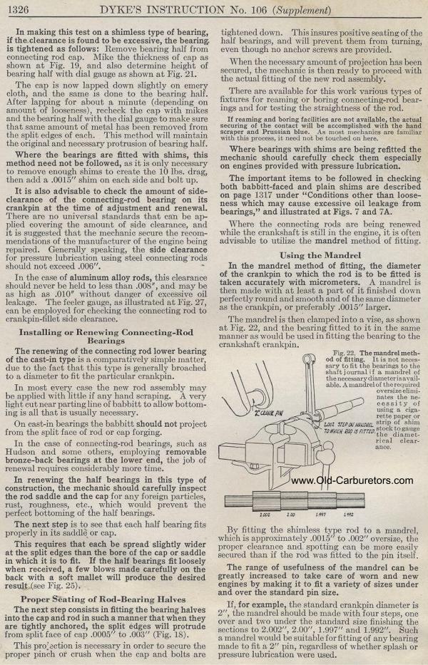
|