valve opens and acts as an air valve during the warming up period.
This prevents overloading and produces a smooth running mixture
with a cold motor.
The accelerating pump, Fig. 248, is of the pneumatic type and consists of a cylinder
with a plunger containing an air bell and two check valves, one on the inlet
and one on the outlet side The upward movement of the plunger, when the throttle
is closed, draws a small metered quantity of fuel into the bottom of the cylinder.
The slightest opening of the throttle causes an immediate discharge through a
jet pointing downward into the main venturi.
Carburetor Adjustment
The carburetors are carefully tested and adjusted
to the engine, before leaving the factory. Too often adjustments
are made to the carburetor, when in reality, something else is
causing uneven running or the engine has not thoroughly warmed
up.
There are two adjustments on the carburetor, one for idling mixture
and the other for idling speed. Both of these adjustments should
be made together.
To adjust the idling mixture, proceed as follows: Open the idle
adjusting screw from % to 1 turn open. Let engine idle. Try turning
screw both ways from this position until the best setting is made.
To adjust for idling speed, proceed as follows: With the hand throttle
on the instrument panel closed, set the throttle lever stop screw
so that the engine runs at approximately 400 revolutions per minute.
I f the engine runs too fast, back the screw out. If too slow,
turn it until the proper speed is obtained.
Accelerating Pump Adjustment
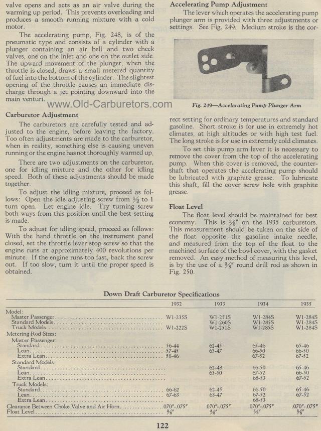
The lever which operates the accelerating pump plunger arm is provided
with three adjustments or settings. See Fig. 249. Medium stroke
is the cor-
Fig. 249— Accelerating Pump Plunger Arm rect
setting for ordinary temperatures and standard gasoline. Short
stroke is for use in extremely hot climates, at high altitudes
or with high test fuel. The long stroke is for use in extremely
cold climates.
To set this pump arm lever it is necessary to remove the cover
from the top of the accelerating pump. When this cover is removed,
the counter-shaft that operates the accelerating pump should be
lubricated with graphite grease. To lubricate this shaft, fill
the cover screw hole with graphite grease.
Float Level
The float level should be maintained for best economy. This is
%" on the 1935 carburetors. This measurement should be taken
on the side of the float opposite the gasoline intake needle, and
measured from the top of the float to the machined surface of the
bowl cover, with the gasket removed. An easy method of measuring
this level, is by the use of a %" round drill rod as shown
in Fig. 250.
Down Draft Carburetor Specifications Read
the table in the page image below.
1932 1933 1934 1935
Model : W1-251S W1-284S WI-284S
Master Passenger W1-235S
Standard Models W1-260S W1-285S W1-284S
Truck Models WI-222S W1-251S W1-285S W1-284S
Metering Rod Sizes: 62-45 65-46 65-46
Master Passenger:
Standard 56-44
Lean 57-45 63-47 66-50 66-50
Extra Lean 58-46 67-52 67-52
Standard Models: 62-48 66-50 65-46
Standard
Lean 63-50 67-52 66-50
Extra Lean 68-53 67-52
Truck Models: 62-45 66-50 65-46
Standard 66-62
Lean 67-63 63-47 67-52 67-52
Extra Lean 68-53
Clearance Between Choke Valve and Air Horn 070"-.075" .070"-.075" .070"-.075" .070"-.075"
Float Level 3/8 "
|