Old Buick Carburetors : BUICK SERIES "50" 1946Previous | Home | Next |
 |
Page 4.
METERING ROD ADJUSTMENT: (Fig. 3) Back out throttle adjusting screw until throttle
valves seat in bores of carbureter. Insert one metering rod gauge T109-152
in place of either metering rod. Press down lightly on vacuum piston link
(A) until lug of piston link (D) contacts lip of metering rod arm (C). There
should be less than .005" clearance between metering rod bearing (B)
and shoulder in notch of metering rod gauge. Adjustment should be made by
bending lip of metering rod arm (C). Use bending tool TI09-105.
Figure 3
Metering Rod Adjustment
UNLOADER ADJUSTMENT: (Figs. 4 and 5) Two adjustments are necessary for correct
unloader setting:
A. Loosen choker lever and screw assembly on choker shaft (H). Insert .020" feeler
gauge (T109-29) between lip on fast idle cam and boss on flange casting (K).
Hold choke valve tightly closed (G) and tighten choker lever and screw assembly
in place.
B. Adjust unloader lip on throttle shaft lever (P) until there is 3/16" clearance
between upper edge of choke valve and inner wall of air horn (N) with throttle
valve held in wide open position. Use gauge T109-28.
FAST IDLE ADJUSTMENT: (Figs. 4 and 5) With choke valve tightly closed (G),
adjust fast idle set screw (L) to give .012" clearance between throttle
valve and bore of carbureter (side opposite port). Be sure fast idle adjusting
screw is on high step of cam (M) when making this. adjustment.
STARTER SWITCH INSTRUCTIONS
AND ADJUSTMENTS
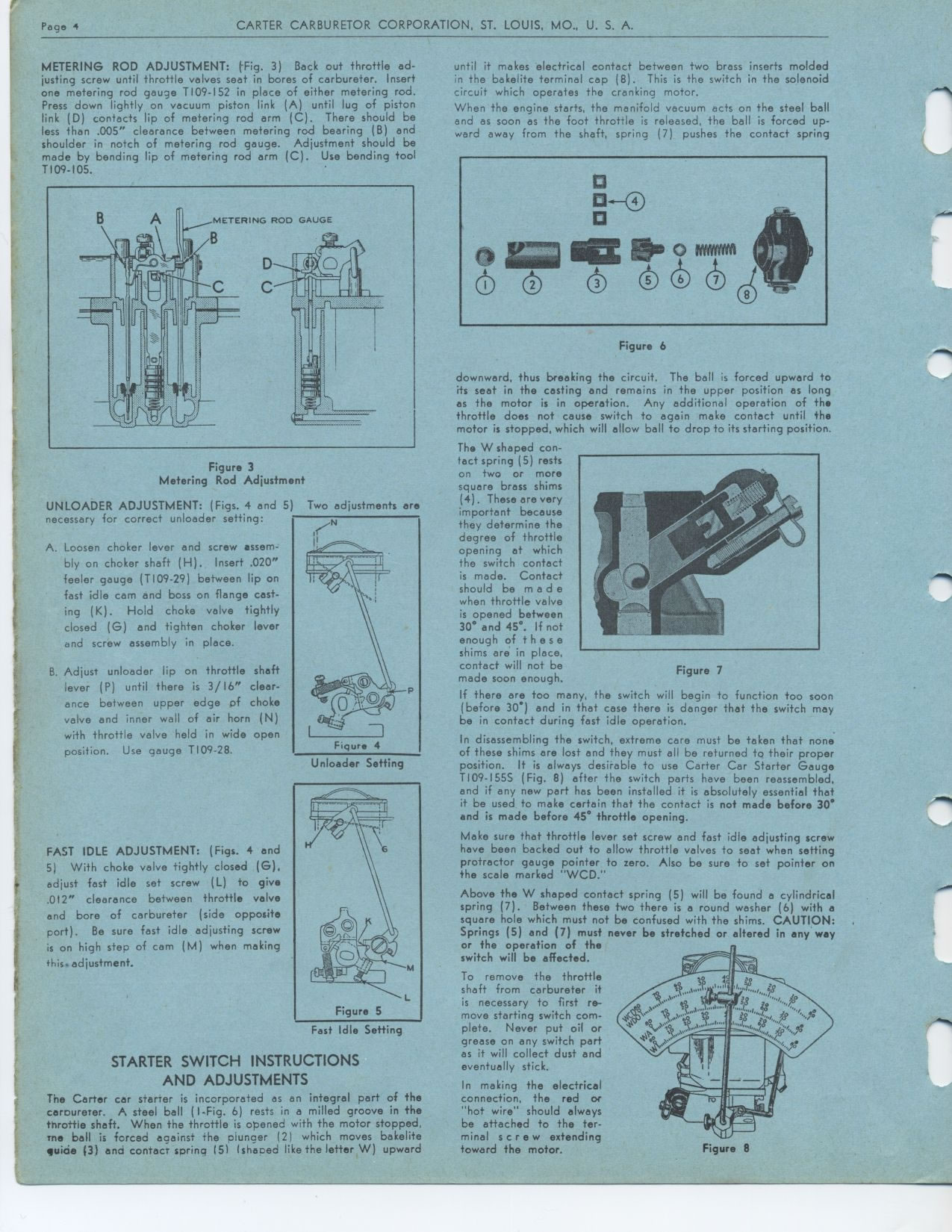
The Carter car starter is incorporated as an integral part of the carbureter.
A steel ball (I-Fig. 6) rests in a milled groove in the throttle shaft. When
the throttle is opened with the motor stopped, me ball is forced against the
plunger (2) which moves bakelite wide (3) and contact spring (51 (shaped like
the letter W) upward
until it makes electrical contact between two brass inserts molded in the bakelite
terminal cap (8). This is the switch in the solenoid circuit which operates
the cranking motor.
When the engine starts, the manifold vacuum acts on the steel ball and as soon
as the foot throttle is released, the ball is forced up-ward away from the
shaft, spring (7) pushes the contact spring
Figure 6
downward, thus breaking the circuit. The ball is forced upward to its seat
in the casting and remains in the upper position as long as the motor is in
operation. Any additional operation of the throttle does not cause switch to
again make contact until the motor is stopped, which will allow ball to drop
to its starting position.
The W shaped con-tact spring (5) rests on two or more square brass shims (4).
These are very important because they determine the degree of throttle opening
at which the switch contact is made. Contact should be made when throttle valve
is opened between 30° and 45°. If not enough of t h e s e shims are
in place, contact will not be made soon enough.
If there are too many, the switch will begin to function too soon (before 30°)
and in that case there is danger that the switch may be in contact during fast
idle operation.
In disassembling the switch, extreme care must be taken that none of these
shims are lost and they must all be returned to their proper position. It is
always desirable to use Carter Car Starter Gauge T109-1555 (Fig. 8) after the
switch parts have been reassembled, and if any new part has been installed
it is absolutely essential that it be used to make certain that the contact
is not made before 30° and is made before 45° throttle opening.
Make sure that throttle lever set screw and fast idle adjusting screw have
been backed out to allow throttle valves to seat when setting protractor gauge
pointer to zero. Also be sure to set pointer on the scale marked "WCD."
Above the W shaped contact spring (5) will be found a cylindrical spring (7).
Between these two there is a round washer (6) with a square hole which must
not be confused with the shims. CAUTION: Springs (5) and (7) must never be
stretched or altered in any way or the operation of the
switch will be affected.
To remove the throttle shaft from carbureter it is necessary to first re-move
starting switch complete. Never put oil or grease on any switch part as it
will collect dust and eventually stick.
In making the electrical connection, the red or "hot wire" should
always be attached to the terminal screw extending toward the motor.
Unloader Setting
Figure 5
Fast Idle Setting
Figure 7
Figure 8