Old Buick Carburetors : BUICK SERIES "50" 1946Previous | Home | Next |
 |
Page 3
Part No. PART NAME List Price
117-83 Vacumeter piston link 15
118-39 Dust cover .. .35
120-65S Metering rod jet and gasket assembly (2) .45
121-78 Coil housing gasket 07
121-79 Body flange gasket 15
121-80 Air horn gasket 15
121-81 Bowl cover gasket ... -- .15
122-70 Pump discharge check plug 30
136-37 Connector rod washer 03
136-38 Throttle shaft washer _ 03
136-53 Switch return spring washer 03
146-1635 —Bowl cover and strainer assembly- 4.75
150-62 Choke piston pin . ° 03
I50A-10 Pin srin --..-.._. .-.... 3 .02
—Parts so marked are new and listed for first time.
Part No. PART NAME List Price
150A-14 Countershaft pin spring 02
153-I I Switch contact spring shim (.018") 02
153-12 Switch contact spring shim (.006") 02
I60-67S Vacumeter piston and pin assembly 45
160-70 Choke piston 35
170N-75S Thermostatic coil and housing assembly 2.20
172-12 Terminal cap hold down clip 15
172-13 Cable clip 15
181-87 Switch guide block 35
181-90S Fast idle cam assembly 45
I84-20S Switch terminal cap assembly ........................... 1.10
186-12 Coil housing baffle plate
15
192-IIU Carter starter switch unit 2.55
196-15 —Pump plunger guide 20
*Gaskets so marked must be soaked in 90 proof denatured alcohol for 15 minutes,
installed on part, and let dry before using.
Small figures in parentheses preceding list price indicate number of pieces used
in carbureter. Where no figure is shown, only one is used.
CARBURETER
FLOAT ADJUSTMENTS: Two separate float adjustments must be made—lateral
and vertical.
LATERAL ADJUSTMENT: With bowl cover assembly inverted, bowl cover gasket removed,
and float lip resting on seated needle, place float gauge T109-162 directly
under float with notched portions of gauge fitted over edges of casting. Floats
should barely touch the vertical uprights of float gauge. Adjustment should
be made by bending arm of float.
VERTICAL ADJUSTMENT: With float gauge in position mentioned above, floats should
just clear the horizontal portion of gauge. Vertical distance between top of
float and machined surface of casting should be 3/16 inch. Adjustment can be
made by bending arm of float. Carefully remove float, install bowl cover gasket
and then reinstall float.
A fast check of the fuel level can be made on the car by removing the inspection
hole plug in the side of carburetor body. Fuel level should be even with the
bottom of the hole—with engine idling.
PUMP ADJUSTMENT: (Fig. I.) The accelerating pump has been designed to produce
a uniform pump action. The total distance the plunger (not shaft) moves from
closed to wide open throttle, controls the amount of fuel discharged. Correct
pump plunger travel is important and should be checked each time the carbureter
is disassembled. Procedure is as follows: With pump connector link in place,
back out throttle lever set screw to allow throttle valves to seat in bores
of carbureter. Support carbureter so throttle can be opened without throttle
levers dragging on bench top (wooden block will suffice). Place pump travel
gauge T109-1175 (E) inverted on edge of dust cover boss of bowl cover. Turn
knurled nut of gauge until finger just touches upper end of plunger shaft.
Read figure on gauge at notch in knurled nut.
Open throttle slowly until plunger bottoms in pump cylinder (at approximately
half throttle). This can be determined by the additional force necessary to
continue to move throttle lever. Relocate pump travel gauge and turn knurled
nut until finger again touches top of plunger shaft. Observe number indicated
on gauge. Hold gauge vertical to Pump Stroke Setting
ADJUSTMENTS
insure correct pump stroke readings. The difference in the two readings obtained should be "21" (21/64" plunger travel).
Adjust by bending throttle connector rod at lower angle (F).
NOTE: It is advisable, before taking pump gauge readings, to practice opening
throttle several times to find position at which increased throttle resistance
indicates plunger bottoming in cylinder.
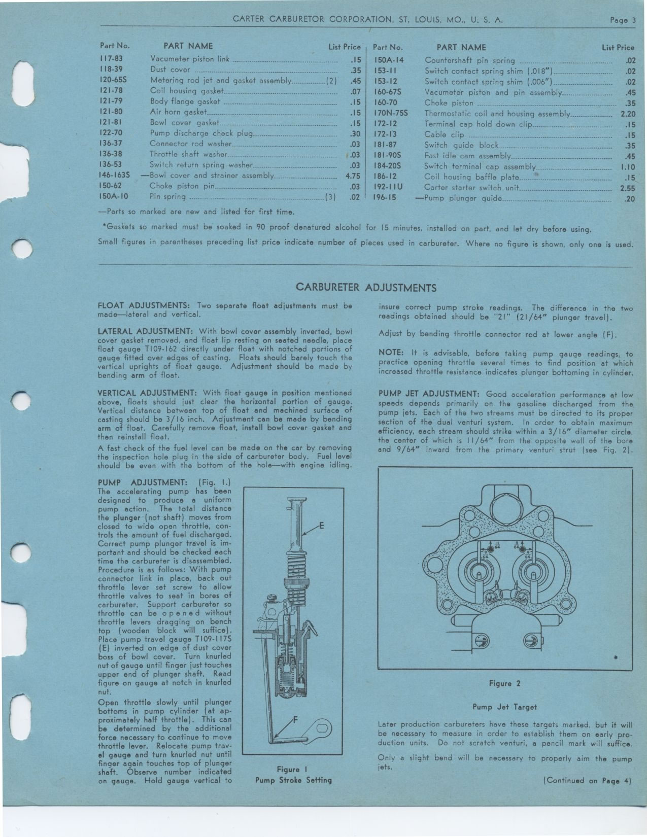
PUMP JET ADJUSTMENT: Good acceleration performance at low speeds depends primarily
on the gasoline discharged from the pump jets. Each of the two streams must
be directed to its proper section of the dual venturi system. In order to obtain
maximum efficiency, each stream should strike within a 3/16" diameter
circle, the center of which is 11/64" from the opposite wall of the bore
and 9/64" inward from the primary venturi strut (see Fig. 2).
Figure 2
Pump Jet Target
Later production carbureters have these targets marked, but it will be necessary
to measure in order to establish them on early production units. Do not scratch
venturi, a pencil mark will suffice.
Only a slight bend will be necessary to properly aim the pump jets.
(Continued on Page 4)
t
Figure I