Old Buick Carburetors : BUICK MODELS 50 60 70 90 1941Previous | Home | Next |
 |
Page 3
CARBURETER ADJUSTMENTS
-7 1. Q
86-12 T 7 101-73 91 1?
96-37 101-19 101-69 101.79 101.84 106109 101-112 101-121 101.136
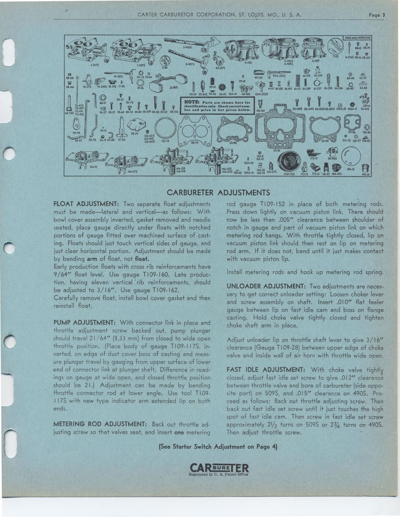
r NOTE: Parts are shown here for identification only. Check correct number
and price in list gi0en below.
101-1485 101-1405 101-1525101-1555 106A-10 105A-0 111-345
53.
153-I2
T
150A-10
146.1215 160.35 .s. A 140-1255 150-02 150A-14 160.70 160-675
172-15 181-905
o e -o
186-12 17242 172-13 '181-82 184-205
19610
FLOAT ADJUSTMENT: Two separate float adjustments must be made—lateral
and vertical—as follows: With bowl cover assembly inverted, gasket removed
and needle seated, place gauge directly under floats with notched portions
of gauge fitted over machined surface of casting. Floats should just touch
vertical sides of gauge, and just clear horizontal portion. Adjustment should
be made by bending arm of float, not float.
Early production floats with cross rib reinforcements have 9/64" float
level. Use gauge T109-160. Late production, having eleven vertical rib reinforcements,
should be adjusted to 3/16". Use gauge T109-162.
Carefully remove float, install bowl cover gasket and then reinstall float.
PUMP ADJUSTMENT: With connector link in place and throttle adjustment screw
backed out, pump plunger should travel 21 /64" (8.33 mm) from closed to
wide open throttle position. (Place body of gauge TI 09- 117S, inverted, on
edge of dust cover boss of casting and measure plunger travel by gauging from
upper surface of lower end of connector link at plunger shaft. Difference in
readings on gauge at wide open, and closed throttle position should be 21.)
Adjustment can be made by bending throttle connector rod at lower angle. Use
tool T109-I I7S with new type indicator arm extended lip on both ends.
METERING ROD ADJUSTMENT: Back out throttle adjusting screw so that valves
seat, and insert one metering
rod gauge T109-152 in place of both metering rods. Press down lightly on vacuum
piston link. There should now be less than .005" clearance between shoulder
of notch in gauge and part of vacuum piston link on which metering rod hangs.
With throttle tightly closed, lip on vacuum piston link should then rest on
lip on metering rod arm. If it does not, bend until it just makes contact with
vacuum piston lip.
Install metering rods and hook up metering rod spring.
UNLOADER ADJUSTMENT: Two adjustments are necessary to get correct unloader setting: Loosen choker lever and screw assembly on shaft. Insert .010" flat feeler gauge between lip on fast idle cam and boss on flange casting. Hold choke valve tightly closed and tighten choke shaft arm in place.
Adjust unloader lip on throttle shaft lever to give 3/16" clearance (Gauge T109-28) between upper edge of choke valve and inside wall of air horn with throttle wide open.
FAST IDLE ADJUSTMENT: With choke valve tightly closed, adjust fast idle set
screw to give .012" clearance between throttle valve and bore of carbureter
(side opposite port) on 509S, and .015" clearance on 490S. Proceed as
follows: Back out throttle adjusting screw. Then back out fast idle set screw
until it just touches the high spot of fast idle cam. Then screw in fast idle
set screw approximately 21/2 turns on 509S or 23/4 turns on 490S. Then adjust
throttle screw.
(See Starter Switch Adjustment on Page 4)