Old Buick Carburetors : BUICK EIGHT MODEL 40r 1941 1942Previous | Home | Next |
 |
an vacuum piston link. Then remove gauge, install metering rods
and attach springs.
UNLOADER ADJUSTMENT: Two adjustments are necessary to get correct unloader
setting:
A. Loosen choker lever and screw assembly on shaft. Insert .010" flat
feeler gauge between lip on fast idle cam and boss on flange casting. Hold
choke valve tightly closed and tighten choke shaft arm in place.
B. Adjust unloader lip on throttle shaft lever to give 3/16" clearance
(Gauge T109-28) between upper edge of choke valve and inside wall of air horn
with throttle wide
open.
FAST IDLE ADJUSTMENT: With choke valve tightly closed, adjust fast idle set
screw to give .012" clearance between throttle valve and bore of carbureter
(side opposite port). Proceed as follows: Back out throttle adjusting screw.
Then back out fast idle set screw until it just touches the high spot of fast
idle cam. Then screw in fast idle set screw 21/ turns. Then adjust throttle
screw.
STARTER SWITCH ADJUSTMENT: Adjustment should be made with Carter tool T109-155S,
obtainable from your Carter distributor with complete instructions.
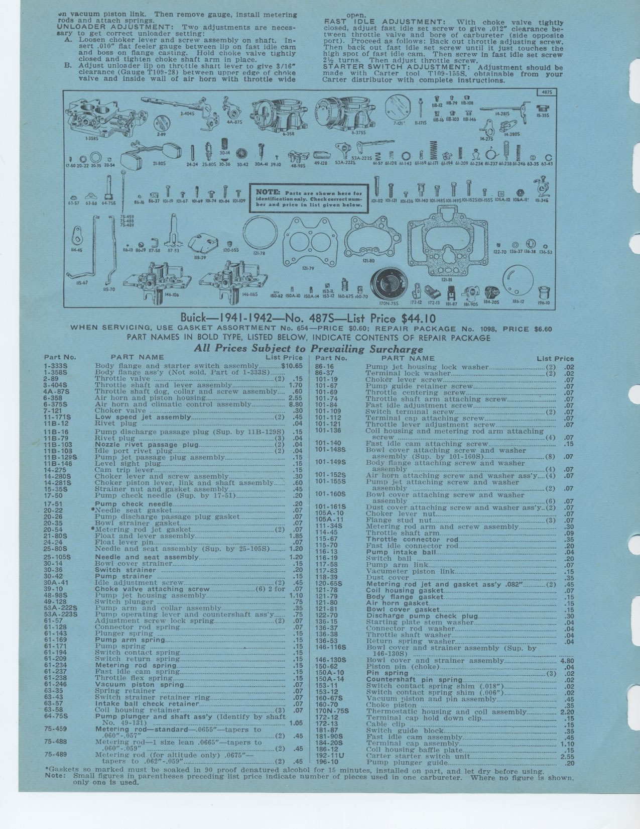
Buick— 1941- 1942—No. 487S—List Price $44. I 0
WHEN SERVICING, USE GASKET ASSORTMENT No. 654—PRICE $0.60; REPAIR PACKAGE
No. 1098, PRICE $6.60 PART NAMES IN BOLD TYPE, LISTED BELOW, INDICATE CONTENTS
OF REPAIR PACKAGE
All Prices Subject to Prevailing Surcharge
Part No. PART NAME List Price Part No. PART NAME List Price
Body flange and starter switch assembly $10 65 86-16 Pump jet housing lock
washer (2) 02
Body flange ass'y (Not sold. Part of 1-333S)_ 86-37 Terminal lock washer (2)
02
Throttle valve - 2) 15 101-19 Choker lever screw 07
Throttle shaft and lever assembly 1 70 101-67 Pump guide retainer screw 07
Throttle shaft dog, collar and screw assembly- -. .60 101-69 Throttle centering
screw 07
Air horn and piston housing 2 55 101-74 Throttle shaft arm attaching screw-
07
Air horn and climatic control assembly 8 80 101-84 Fast idle adjustment screw
07
Choker valve - .30 101-109 Switch terminal screw °- (2) .07
45 101-112 Terminal cap attaching screw 07
04 101-121 Throttle lever adjustment screw 07
15 101-136 Coil housing and metering rod arm attaching
screw -----------------------------------° (4)
Fast idle cam attaching screw :
Bowl cover attaching screw and washer
assembly (Sup. by 101-160S) (8)
Body flange attaching screw and washer
assembly ° ° (4)
Air horn attaching screw and washer ass'y....(4) Pump jet attaching screw and
washer
assembly ...---... ...----° (2)
Bowl cover attaching screw and washer
assembly ... .---- (6) .07
101-161S Dust cover attaching screw and washer ass'y..(2) .07
105A-10 Choker lever nut 07
105A-11 Flange stud nut (3) .07
111-34S Metering rod arm and screw assembly 30
114-45 Throttle shaft arm 09
115-67 Throttle connector rod 35
115-70 Fast idle connector rod 20
116-13 Pump intake ball 04
116-19 Switch ball . .... .20
117-58 Pump arm link - 07
117-83 Vacumeter piston link 15
118-39 Dust cover 35
120-65S Metering rod jet and gasket ass'y .082" (2) 45
121-78 Coil housing gasket 07
121-79 Body flange gasket 15
121-80 Air horn gasket .............................°---°..° °--
15
121-81 Bowl cover gasket 15
122-70 Discharge pump check plug 30
136-15 Starting plate stem washer 04
136-37 Connector rod washer 04
136-38 Throttle shaft washer 04
136-53 Return spring washer 04
146-116S Bowl cover and strainer assembly (Sup. by
146-130S) - - --°--- ---°- - --... --°-°--° °°----
Bowl cover and strainer assembly 4 80
Piston pin (choke) 04
Pin spring .................°...(3) 02
Countershaft pin spring 02
Switch contact spring shim (.018") 02
Switch contact spring shim (.006") 02
Vacuum piston and pin assembly 45
Choke piston .... .-.... . .35
Thermostatic housing and coil assembly 2 20
Terminal cap hold down clip 15
Cable clip ° 15
Switch guide block 35
Fast idle cam assembly 45
Terminal cap assembly 1 10
.060-.059 (2) .45 186-12 Coil housing baffle plate 15
Metering rod (for altitude only) .0675"— 192-11U Carter starter switch
unit 2 55
tapers to .062"-.059" (2) .45 196-10 Pump plunger guide ..... ° ....
.20
"Gaskets so marked must be soaked in 90 proof denatured alcohol for 15 minutes,
installed on part, and let dry before using.
Note: Small figures in parentheses preceding list price indicate number of pieces
used in one carbureter. Where no figure is shown, only one is used.
4875
1184 IIB-12 118.79 II8408
'9' 14.2815
121' II-1715 118-Ib I15-103 118-146
53A-2235
5336-2225 . 61.57 61.124 61-143 61-1696:-171 61.194 61-209 61-23461-23761-23861-24663-35
63-43
6I
63-57 63-58 64-756
8646 86-37 101.19 101-67 101-69 101-74 10684 101-109
NOTE: Parts are shown here for identification only. Check correct number and
price in list given below.
E
101-112 101121 101.136 101.140 101-1485101-1495101-1525101-1555 10536-10 10536-111
111-346
114.45
pal
115-67
4o
121.79
II 1533-IgE -1t
150-62 I5036-10 I5036-14 153-12 160-675 X60-70
186.12
196-10
1-333S 1-358S 2-89 3-404S 4A-87S 6-358 6-375S 7-121 11-171S 11B-12
11B-16 11B-79 11B-103 11B-103 11B-129S 11B-146 14-275 14-280S 14-281S 15-35S
17-50
17-51 20-22 20-26 20-35 20-54 21-80S 24-24 25-80S
25-105S 30-14 30-36 30-42 30A-41 39-10 48-98S 49-128 53A -222S 53A-223S 61-57
61-128 61-143 61-169 61-171 61-194 61-209 61-234 61-237 61-238 61-246 63-35 63-43
63-57 63-58 64-75S
75-459 75-488 75-489
Low speed jet assembly (2)
Rivet plug --° -
Pump discharge passage plug (Sup. by 11B-129S)
Rivet plug --- --_-• (3) 04
Nozzle rivet passage plug (2) 04
Idle port rivet plug (2) 04
Pump jet passage plug assembly 15
Level sight plug 15
Cam trip lever °--- 15
Choker lever and screw assembly 30
Choker piston lever, link and shaft assembly 60
Strainer nut and gasket assembly 45
Pump check needle (Sup. by 17-51) 20
Pump check needle 20
*Needle seat gasket . .07
Pump discharge passage plug gasket 07
Bowl strainer gasket 07
•Metering rod jet gasket - (2) 07
Float and lever assembly 1 85
Float lever pin ° ° .07
Needle and seat assembly (Sup. by 25-105S) 1 20
Needle and seat assembly 1 20
Bowl cover strainer 15
Switch strainer 20
Pump strainer --------------. . .°--°-.---.--- 15
Idle adjustment screw (2) 45
Choke valve attaching screw (6) 2 for 07
Pump jet housing assembly 1 10
Switch plunger ------- -----... . .75
Pump arm and collar assembly.__ .. 35
Pump operating lever and countershaft ass'y 75
Adjustment screw lock spring (2) 07
Connector rod spring ....---- ---- 07
Plunger spring ---- °°---° °° .. . .15
Pump arm spring 15
Pump spring ................................ .15
Switch contact spring 15
Switch return spring 15
Metering rod spring 15
Fast idle cam spring ....................... .15
Throttle flex spring 15
Vacuum piston spring 07
Spring retainer .. ........................................................ .07
Switch strainer retainer ring 07
Intake ball check retainer 07
Coil housing retainer (3) .07
Pump plunger and shaft ass'y (Identify by shaft
No. 49-131) --- _.... 1.05
Metering rod-standard—.0655"—tapers to
.060"-.057" (2) .45
Metering rod—1 size lean .0665"—tapers to