Old Buick Carburetors : BUICK EIGHT MODEL 40r 1941 1942Previous | Home | Next |
 |
Form 6470B—Canadian
BUICK 487$
January, 1941
Reprinted April, 1946
MOTOR SERIAL NUMBER
44074861 and higher
CAR SERIAL NUMBER 13880023 and higher
U. S. Production
BUICK
EIGHT
MODEL 40r
1941 1942
Superseded by 608S
Imported and Tourist
Cars Only
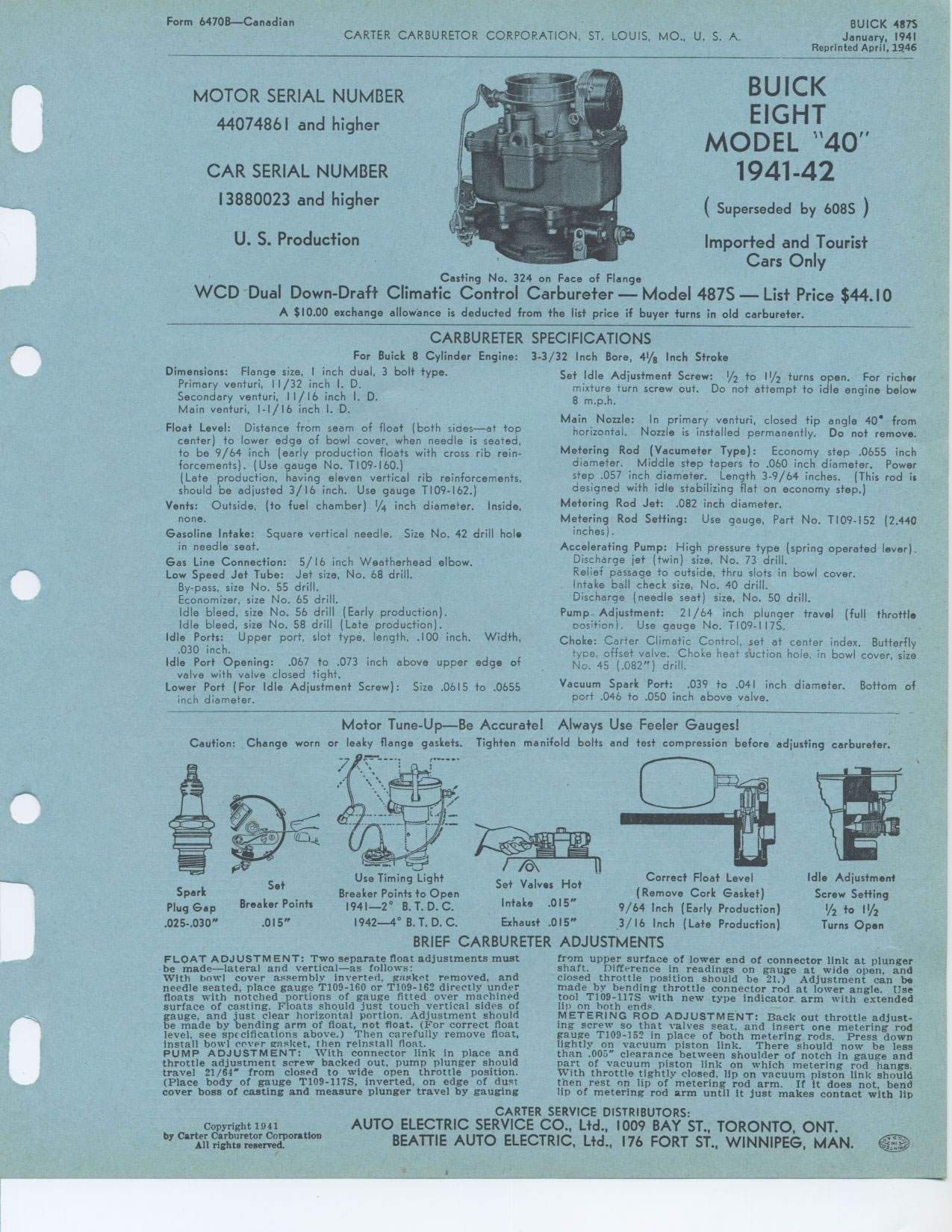
Casting No. 324 on Face of Flange
WCD Dual Down-Draft Climatic Control Carbureter — Model 487S — List
Price $44.10
A $10.00 exchange allowance is deducted from the list price if buyer turns
in old carbureter.
CARBURETER
For Buick 8 Cylinder Engine: Dimensions: Flange size, 1 inch dual, 3 bolt type.
Primary venturi, 11/32 inch I. D.
Secondary venturi, 11/16 inch I. D.
Main venturi, I-I/16 inch I. D.
Float Level: Distance from seam of float (both sides—at top center) to
lower edge of bowl cover, when needle is seated, to be 9/64 inch (early production
floats with cross rib reinforcements). (Use gauge No. T109-160.)
(Late production, having eleven vertical rib reinforcements, should be adjusted
3/16 inch. Use gauge T109-162.)
Vents: Outside, (to fuel chamber) V/4 inch diameter. Inside, none.
Gasoline Intake: Square vertical needle. Size No. 42 drill hole in needle seat.
Gas Line Connection: 5/ 16 inch Weatherhead elbow. Low Speed Jet Tube: Jet
size, No. 68 drill.
By-pass, size No. 55 drill.
Economizer, size No. 65 drill.
Idle bleed, size No. 56 drill (Early production).
Idle bleed, size No. 58 drill (Late production).
Idle Ports: Upper port, slot type, length, .100 inch. Width, .030 inch.
Idle Port Opening: .067 to .073 inch above upper edge of valve with valve closed
tight.
Lower Port (For Idle Adjustment Screw): Size .0615 to .0655 inch diameter.
SPECIFICATIONS
3-3/32 Inch Bore, 41/8 Inch Stroke
Set Idle Adjustment Screw: V2 to 11/2 turns open. For richer mixture turn screw
out. Do not attempt to idle engine below 8 m.p.h.
Main Nozzle: In primary venturi, closed tip angle 40' from horizontal. Nozzle
is installed permanently. Do not remove.
Metering Rod (Vacumeter Type): Economy step .0655 inch diameter. Middle step
tapers to .060 inch diameter. Power step .057 inch diameter. Length 3-9/64
inches. (This rod is designed with idle stabilizing flat on economy step.)
Metering Rod Jet: .082 inch diameter.
Metering Rod Setting: Use gauge, Part No. T109-152 (2.440 inches).
Accelerating Pump: High pressure type (spring operated lever). Discharge jet
(twin) size, No. 73 drill.
Relief passage to outside, thru slots in bowl cover.
Intake ball check size, No. 40 drill.
Discharge (needle seat) size, No. 50 drill.
Pump Adjustment: 21/64 inch plunger travel (full throttle oosition). Use gauge
No. T109-I17S.
Choke: Carter Climatic Control, set at center index. Butterfly type, offset
valve. Choke heat suction hole, in bowl cover, size No. 45 (.082") drill.
Vacuum Spark Port: .039 to .041 inch diameter. Bottom of port .046 to .050
inch above valve.
Motor Tune-Up—Be Accurate! Always Use Feeler Gauges!
Caution: Change worn or leaky flange gaskets. Tighten manifold bolts and test
compression before adjusting carbureter.
BRIEF CARBURETER ADJUSTMENTS
Idle Adjustment Screw Setting
/2 to 13/2
Turns Open
m!'T #n !Wall
Correct Float Level
(Remove Cork Gasket)
9/64 Inch (Early Production)
3/16 Inch (Late Production)
Use Timing Light
Breaker Points to Open 1941—2° B. T. D. C. 1942—4° B. T.
D. C.
Set Valves Hot Intake .015" Exhaust .015"
Spark Plug Gap .025-.030"
Set
Breaker Points
.015"
FLOAT ADJUSTMENT: Two separate float adjustments must be made—lateral
and vertical—as follows:
With bowl cover assembly Inverted, gasket removed, and needle seated, place
gauge T109-160 or T109-162 directly under floats with notched portions of gauge
fitted over machined surface of casting. Floats should just touch vertical
sides of gauge, and just clear horizontal portion. Adjustment should be made
by bending arm of float, not float. (For correct float level, see specifications
above.) Then carefully remove float, install bowl cover gasket, then reinstall
float.
PUMP ADJUSTMENT: With connector link in place and throttle adjustment screw
backed out, pump plunger should travel 21/64" from closed to wide open
throttle position. (Place body of gauge T109-117S, inverted, on edge of dust
cover boss of casting and measure plunger travel by gauging
from upper surface of lower end of connector link at plunger shaft. Difference
in readings on gauge at wide open, and
closed throttle position should be 21.) Adjustment can be made by bending throttle
connector rod at lower angle. Use tool T109-117S with new type indicator arm
with extended
lip on both ends.
METERING ROD ADJUSTMENT: Back out throttle adjusting screw so that valves seat.
and insert one metering rod gauge T109-152 in place of both metering rods.
Press down
lightly on vacuum piston link. There should now be less than .005" clearance
between shoulder of notch in gauge and part of vacuum piston link on which
metering rod hangs. With throttle tightly closed, lip on vacuum piston link
should
then rest on lip of metering rod arm. If it does not, bend lip of metering
rod arm until it just makes contact with lip
Copyright 1941