Old Buick Carburetors : BUICK EIGHT MODEL 40 & 50 1940Previous | Home | Next |
 |
1
closed and adjust fast idle arm screw to give .030" opening between edge
of throttle valve and bore of carburetor, side opposite port. (Use gauge T109-29.)
THROTTLE STOP DOG ADJUSTMENT: With choke valve
open, close throttle valve. Then close choker valve and adjust lip on throttle
stop dog to contact throttle stop (4A-82) at 4.4° minimum or 55° maximum
throttle opening, from tightly closed throttle position. Use gauge T109-121S.
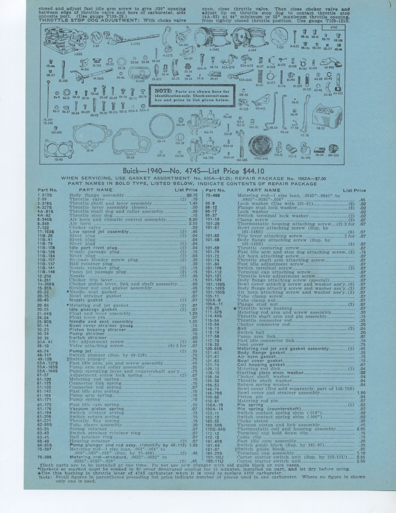
Buick—I940—No. 474S—List Price $44.10
WHEN SERVICING, USE GASKET ASSORTMENT No. 635A—$1.25; REPAIR PACKAGE
No. 1062A—$7.00 PART NAMES IN BOLD TYPE, LISTED BELOW, INDICATE CONTENTS
OF REPAIR PACKAGE
Metering rod—1 size lean, .0645"-.0645" to
.0605"-.0595"-.056"
Lock washer (Use with 101-61) (6)
Flange stud lock washer (3)
Lock washer ° - °--- ---
Switch terminal lock washer (2)
Clamp screw (2)
Thermostatic housing attaching screw....(2) 2 for Bowl cover attaching screw
(Sup. by
101-148S) ------ ....................:(6)
Trip lever attaching screw 2 for
Body flange attaching screw (Sup. by
101-149S) ...........................................................(3) 07
101-69 Throttle centering screw 07
101-70 Fast idle arm and stop dog attaching screw (2) 15
101-72 Air horn attaching screw 07
101.74 Throttle shaft arm attaching screw 07
101 -84 Fast idle adjustment screw - .07
101-109 Switch terminal screw (2) 07
101-112 Terminal cap attaching screw 07
101-121 Throttle lever adjustment screw 07
101-124 Body flange attaching screw (special) 07
101-148S Bowl cover attach'g screw and washer ass'y..(6) 07
101-1495 Body flange attach'g screw and washer ass'y..(3) 07
101-150S Air horn attaching screw and washer ass'y..(2) 07
105-11 Tube clamp screw 07
105A-8 Tube clamp nut. 07
105A-11 Flange stud nut .........................................................
(3) 07
108.25 *Throttle lever bushing 07
111-32S Metering rod arm and screw assembly 30
114.44S Throttle shaft arm and pin assembly 15
115-54 Throttle connector rod 35
115-64 Choker connector rod_ 20
116-13 Ball (2) .04
116-19 Switch hall --- .................................... .20
117-58 Pump arm link 07
117-79 Fast idle connector link 15
118-33 Dust cover 75
120-65S Metering rod jet and gasket assembly (2) 45
121-43 Body flange gasket 35
121-61 Air horn gasket 15
121 -63 Bowl cover gasket 15
121.74 Coil housing gasket 07
129-12 M hiring rod disk disk ..................................................
(2) 04
136-15 Starting plate stem washer 02
136-34 Choker shaft washer 04
136-38 Throttle shaft washer 04
136-53 Return spring washer 04
146-74 Bowl cover (Not sold separately, part of 146-79S)
146-79S Bowl cover and strainer assembly 1 90
150-62 Piston pin 04
150-81 Metering rod pin 07
150A-10 Pin spring (5) 02
150A-14 Pin spring (countershaft) 02
153-11 Switch contact spring shim (.018") 02
153-12 Switch contact spring shim (.006") 02
160.35 Choke piston 30
160-58S Vacuum piston and link assembly 45
170G-64S Thermostatic coil and housing assembly 2 95
172-12 Terminal cap hold down clip 15
172-13 Cable clip 15
181-49S Fast idle cam assembly 20
181.64 Switch guide block (Sup• by 181-87) 35
181-87 Switch guide bloak °..°--- 35
184.205 Terminal cap assembly 1 10
Metering red—standard, .0635 -.0635 to - 192-10U Carter starter switch
unit (Sup. by 192-11U) - 2 55
.0595"-.0595"-.056" _(2) 45 192-11U Carter starter switch unit
2 55
*Both parts are to he installed at one time. Do not use new plunger with old
guide block or vice versa.
.Gaskets so marked must be soaked in 917 proof denatured alcohol for 15 minutes,
installed on part, and let dry before using. *Use this bushing in throttle
lever of 474S carbureter when It is need to replace 440S carhureter.
Note: Small figures in parentheses preceding list price indicate number of
pieces used in one carbureter. Where no figure is shown only one is used.
NOTE: Parts are shown here for identification only. Check correct numbar and
price in list given below.
Part No. 1 313S 2-89 3-379S 4.3275 4A-81S 4A-82 6-344S 6-349 7-122 11.163S
118 -26 11B-41 11B 79 11B-108 11 B-126 11B-134 11B - 157 11B-137 11B-141 11B-146
12-250 14-261 14-266S 15-35S 20-22 20-35 20-45
20-54 20-55 21-64S 24-24 25-80S 30-14 30-23 30.34 30 36 30A-41 39-10
PART NAME List Price
Body flange assembly $8.10
Throttle valve (2) .15
Throttle shaft and lever assembly 1.45
Throttle lever assembly (loose) 50
Throttle shaft dog and collar assembly 30
Throttle stop dog 15
Air horn and climatic control assembly 8 80
Air horn _ ° ............................................ 2 55
Choker valve -' ................................................ .30
Low speed jet assembly (2) 45
Rivet plug (2) 04
Rivet plug 04
Rivet plug (5) 04
Idle port rivet plug (2) 04
Nozzle passage plug (2) 15
Ric it plug .....°--_ (2) 04
by-tease bleeder screw plug (2) 30
Ball retainer plug 30
Nozzle retainer plug (2) 15
Pump jet passage plug (2) 15
Nozzle -(2) 45
Choker trip lover 15
Choker piston lever, link and shaft assembly_ 60
Strainer nut and gasket assembly 45
• Needle seat gasket 07
Bowl strainer gasket 07
Nozzle gasket (2) 07
* Metering red jet gasket (2) 07
Idle passage gasket (3) 07
bloat and lever assembly 1 20
Float lever pin 07
Needle and seat assembly 1 20
Bowl rover strainer gauze 15
Piston housing strainer 20
Pump strainer -- .15
Switch strainer -' 20
I•ll' adjustment screw (2) 45
Valve attaching screw (6) 2 for 07
48-74 Pump Jet -(2) 35
49-117 Switch plunger (Sup. by 49-128) 75
49-128 *Switch plunger 75
53A-127S Fast idle arm, pin and screw assembly 45
53A-163S Pump arm and collar assembly 35
53A-164S Pump operating lever and countershaft ass'y 75
61-57 Adjustment screw lock spring...._t (2) 07
61.120 Metering rod spring 15
61-123 Connector link spring 15
61-128 Connector rod spring 07
61-142 Fast idle arm spring 15
61-169 Punta arm spring- 15
61-171 Pump spring ---- ------- .15
75-398
Foist idle earn spring 15
Vacuum piston spring 07
Switch cr,ntaet 15
Switch return siring 15
Throttle flex spring ----- .15
Tube clamn assembly 30
Spring retainer _ 07
Switch strainer retainer ring 07
Ball retainer ring 07
Housing retainer (2) 07
Pump plunger and rod assy. (Identify by 49-113) 1 05
Metering rod1 size lean. .014"-.064" to
,060"-.060"-.056" (Sup. by 75-468) (2) 45