Old Buick Carburetors : BUICK EIGHT MODELS 60 70 80 90 1940Previous | Home | Next |
 |
Form 6448A—Canadian
UICK 448S
July, 1940
Reprinted March, 1945
BUICK EIGHT
MODELS 60 70 80 90
1940
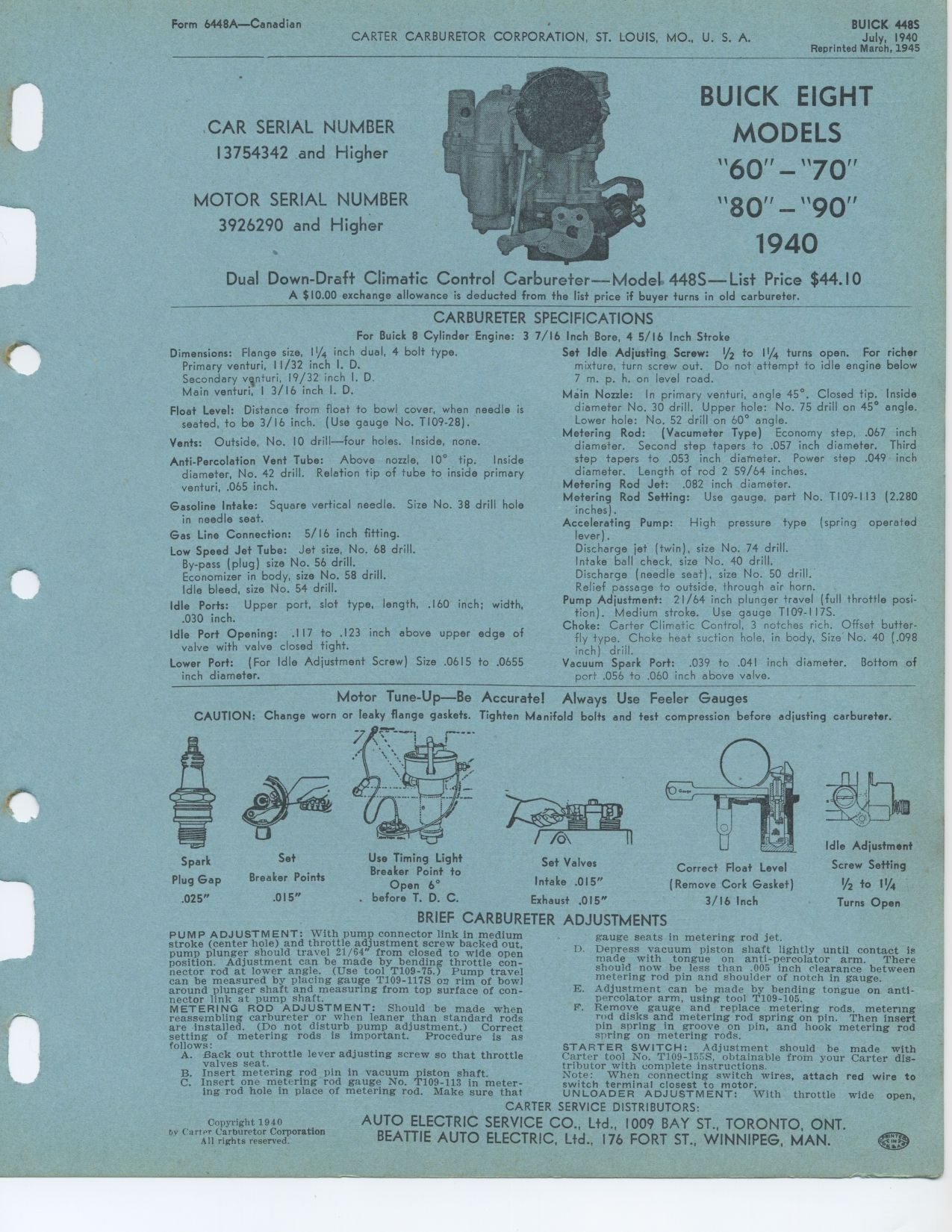
Dual Down-Draft Climatic Control Carbureter—Model 448S—List Price
$44.10
A $10.00 exchange allowance is deducted from the list price if buyer turns
in old carbureter.
CAR SERIAL NUMBER 13754342 and Higher
MOTOR SERIAL NUMBER
3926290 and Higher
CARBURETER
For Buick 8 Cylinder Engine: 3 Dimensions: Flange size, 11/4 inch dual, 4 bolt
type.
Primary venturi, 11/32 inch I. D.
Secondary venturi, 19/32 inch I. D.
Main venturi, 13/16 inch I. D.
Float Level: Distance from float to bowl cover, when needle is seated, to be
3/16 inch. (Use gauge No. T109-28).
Vents: Outside, No. 10 drill—four holes. Inside, none.
Anti-Percolation Vent Tube: Above nozzle, 10° tip. Inside diameter, No.
42 drill. Relation tip of tube to inside primary venturi, .065 inch.
Gasoline Intake: Square vertical needle. Size No. 38 drill hole in needle seat.
Gas Line Connection: 5/ 16 inch fitting.
Low Speed Jet Tube: Jet size, No. 68 drill.
By-pass (plug) size No. 56 drill.
Economizer in body, size No. 58 drill.
Idle bleed, size No. 54 drill.
Idle Ports: Upper port, slot type, length, .160 inch; width,
.030 inch.
Idle Port Opening: .117 to .123 inch above upper edge of valve with valve closed
tight.
Lower Port: (For Idle Adjustment Screw) Size .0615 to .0655 inch diameter.
SPECIFICATIONS
7/16 Inch Bore, 4 5/16 Inch Stroke
Set Idle Adjusting Screw: 1/2 to 11/4 turns open. For richer mixture, turn
screw out. Do not attempt to idle engine below 7 m. p. h. on level road.
Mein Nozzle: In primary venturi, angle 45°. Closed tip. Inside diameter
No. 30 drill. Upper hole: No. 75 drill on 45° angle. Lower hole: No. 52
drill on 60° angle.
Metering Rod: (Vacumeter Type) Economy step, .067 inch diameter. Second step
tapers to .057 inch diameter. Third step tapers to .053 inch diameter. Power
step .049 inch diameter. Length of rod 2 59/64 inches.
Metering Rod Jet: .082 inch diameter.
Metering Rod Setting: Use gauge, part No. T109-113 (2.280 inches).
Accelerating Pump: High pressure type (spring operated lever).
Discharge jet (twin), size No. 74 drill.
Intake ball check, size No. 40 drill.
Discharge (needle seat), size No. 50 drill.
Relief passage to outside, through air horn.
Pump Adjustment: 21/64 inch plunger travel (full throttle position). Medium
stroke. Use gauge T109-117S.
Choke: Carter Climatic Control, 3 notches rich. Offset butter-fly type. Choke
heat suction hole, in body, Size No. 40 (.098 inch) drill.
Vacuum Spark Port: .039 to .041 inch diameter. Bottom of port .056 to .060
inch above valve.
Motor Tune-Up—Be Accurate! Always Use Feeler Gauges
CAUTION: Change worn or leaky flange gaskets. Tighten Manifold bolts and test
compression before adjusting carbureter.
Spark Plug Gap .025"
Set
Breaker Points
.015"
Use Timing Light
Breaker Point to
Open 6°
before T. D. C.
Set Valves Intake .015" Exhaust .015"
Correct Float Level
(Remove Cork Gasket)
3/16 Inch
Idle Adjustment Screw Setting
I/2 to 1114 Turns Open
BRIEF CARBURETER ADJUSTMENTS
PUMP ADJUSTMENT: With pump connector link in medium stroke (center hole) and
throttle adjustment screw backed out, pump plunger should travel 21/64" from
closed to wide open position. Adjustment can be made by bending throttle connector
rod at lower angle. (Use tool T109-75.) Pump travel can be measured by placing
gauge T109-1175 on rim of bowl around plunger shaft and measuring from top
surface of connector link at pump shaft.
METERING ROD ADJUSTMENT: Should be made when reassembling carbureter or when
leaner than standard rods are installed. (Do not disturb pump adjustment.)
Correct setting of metering rods is important. Procedure is as follows:
A. Back out throttle lever adjusting screw so that throttle valves seat.
B. Insert metering rod pin in vacuum piston shaft.
C. Insert one metering rod gauge No. T109-113 in metering rod hole in place
of metering rod. Make sure that
Copyright 1940
tot Carter Carburetor Corporation
All rights reserved.
gauge seats in metering rod jet.
D. Depress vacuum piston shaft lightly until contact is made with tongue on
anti-percolator arm. There should now be less than .005 inch clearance between
metering rod pin and shoulder of notch in gauge.
E. Adjustment can be made by bending tongue on anti-percolator arm, using tool
T109-105.
F. Remove gauge and replace metering rods. metering rod disks and metering
rod spring on pin. Then insert pin spring in groove on pin, and hook metering
rod spring on metering rods.
STARTER SWITCH: Adjustment should be made with Carter tool No. T109-1555, obtainable
from your Carter distributor with complete instructions.
Note: When connecting switch wires, attach red wire to switch terminal closest
to motor.
UNLOADER ADJUSTMENT: With throttle wide open,