Chevrolet with Old Carter Carburetors : CHEVROLET & G. M. C. TRUCKS 1939 19 40 1941Previous | Home | Next |
 |
Form 6395C—Canadian
CHEVROLET 447S
July, 1939
Reprinted March, 1945
TRUCK SERIAL NUMBERS
1939 1940 1941
Chevrolet—9 18-00001
G.M.C.—998-0000 I
1941
Chevrolet Series 1800 (C.O.E.)
Oshawa 118—05001 to 118-10231
Regina I I—80001 and higher
G.M.C. Series 9800 (C.O.E.)
198—00001 to 198-01876
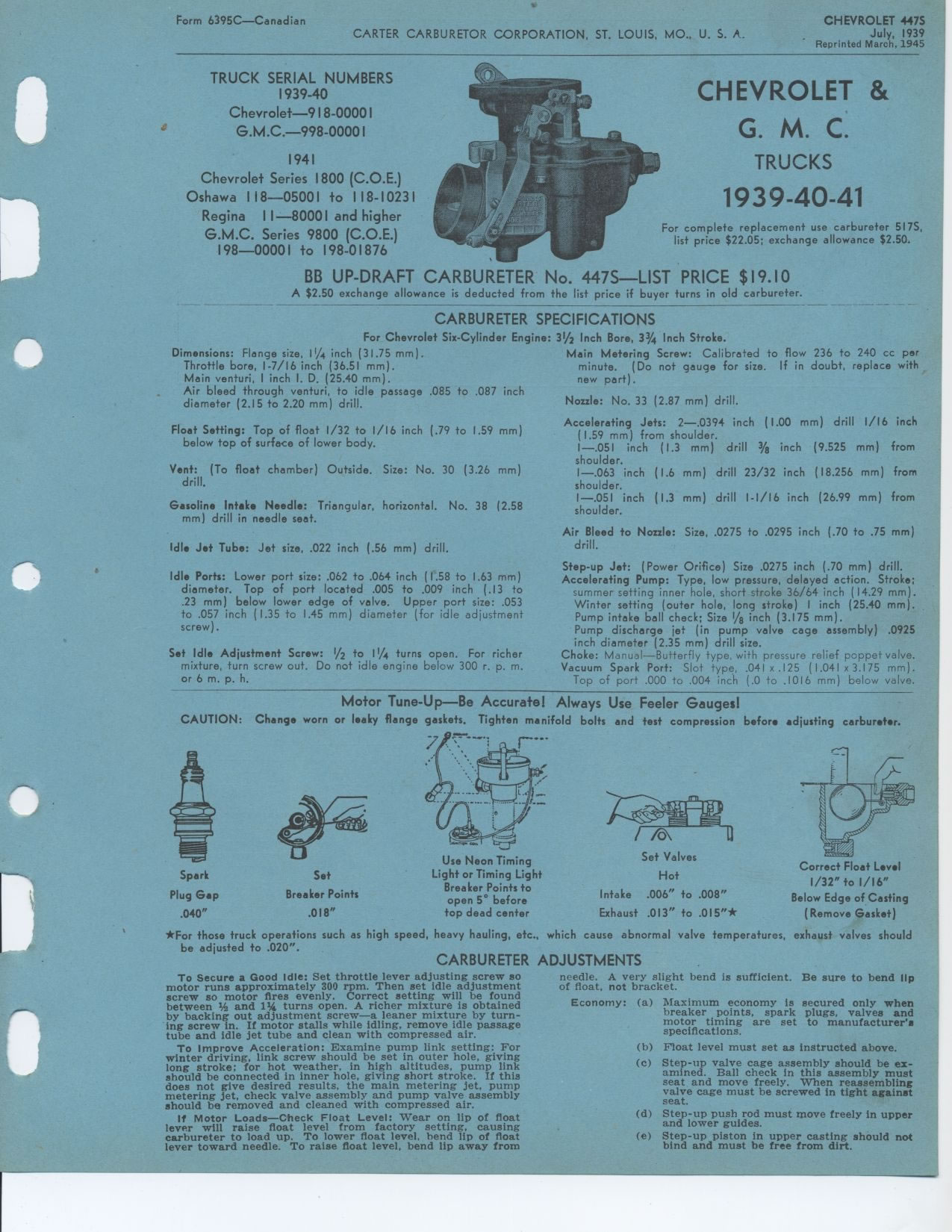
BB UP-DRAFT CARBURETER No. 447S—LIST PRICE $19.10
A $2.50 exchange allowance is deducted from the list price if buyer turns in
old carbureter.
CARBURETER SPECIFICATIONS
For Chevrolet Six-Cylinder Engine: 31/2 Inch Bore, 33/4 Inch Stroke.
CHEVROLET &
G. M. C.
TRUCKS
1939 19 40 1941
For complete replacement use carbureter 517S,
list price $22.05; exchange allowance $2.50.
Dimensions: Flange size, li// inch (31.75 mm).
Throttle bore, 1-7/16 inch (36.51 mm).
Main venturi, I inch I. D. (25.40 mm).
Air bleed through venturi, to idle passage .085 to .087 inch diameter (2.15
to 2.20 mm) drill.
Float Setting: Top of float 1/32 to 1/16 inch (.79 to 1.59 mm) below top
of surface of lower body.
Vent: (To float chamber) Outside. Size: No. 30 (3.26 mm) drill.
Gasoline Intake Needle: Triangular, horizontal. No. 38 (2.58 mm) drill in
needle seat.
Idle Jet Tube: Jet size, .022 inch (.56 mm) drill.
Idle Ports: Lower port size: .062 to .064 inch (1.58 to 1.63 mm) diameter.
Top of port located .005 to .009 inch (.13 to .23 mm) below lower edge of valve.
Upper port size: .053 to .057 inch (1.35 to 1.45 mm) diameter (for idle adjustment
screw).
Set Idle Adjustment Screw: 1/2 to 11/4 turns open. For richer mixture, turn
screw out. Do not idle engine below 300 r. p. m. or 6 m. p. h.
Main Metering Screw: Calibrated to flow 236 to 240 cc per minute. (Do not gauge
for size. If in doubt, replace with new part).
Nozzle: No. 33 (2.87 mm) drill.
Accelerating Jets: 2—.0394 inch (1.00 mm) drill 1/16 inch (1.59 mm) from
shoulder.
—.051 inch (1.3 mm) drill 3/8 inch (9.525 mm) from shoulder.
—.063 inch (1.6 mm) drill 23/32 inch (18.256 mm) from shoulder.
—.051 inch (1.3 mm) drill I-1/16 inch (26.99 mm) from shoulder.
Air Bleed to Nozzle: Size, .0275 to .0295 inch (.70 to .75 mm) drill.
Step-up Jet: (Power Orifice) Size .0275 inch (.70 mm) drill.
Accelerating Pump: Type, low pressure, delayed action. Stroke; summer setting
inner hole, short stroke 36/64 inch (14.29 mm). Winter setting (outer hole,
long stroke) I inch (25.40 mm). Pump intake ball check; Size 1/8 inch (3.175
mm).
Pump discharge jet (in pump valve cage assembly) .0925 inch diameter (2.35
mm) drill size.
Choke: Manual—Butterfly type, with pressure relief poppet valve.
Vacuum Spark Port: Slot type, .041 x .125 (1.041 x 3.175 mm).
Top of port .000 to .004 inch (.0 to .1016 mm) below valve.
Motor Tune-Up—Be Accurate! Always Use Feeler Gauges!
CAUTION: Change worn or leaky flange gaskets. Tighten manifold bolts and test
compression before adjusting carburetor.
Spark Plug Gap .040"
Set
Breaker Points
.018"
Use Neon Timing Light or Timing Light
Breaker Points to
open 5° before
top dead center
Correct Float Level
1/32" to 1/16"
Below Edge of Casting
(Remove Gasket)
Set Valves
Hot
Intake .006" to .008" Exhaust .013" to .015"*
*For those truck operations such as high speed, heavy hauling, etc., which
cause abnormal valve temperatures, exhaust valves should be adjusted to .020".
CARBURETER ADJUSTMENTS
To Secure a Good Idle: Set throttle lever adjusting screw so needle. A very
slight
motor runs approximately 300 rpm. Then set idle adjustment of float, not bracket.
screw so motor fires evenly. Correct setting will be found between 1/a and
1% turns open. A richer mixture is obtained by backing out adjustment screw—a
leaner mixture by turning screw in. If motor stalls while idling, remove idle
passage tube and idle jet tube and clean with compressed air.
To Improve Acceleration: Examine pump link setting: For winter driving, link
screw should be set in outer hole, giving long stroke; for hot weather, in
high altitudes, pump link should be connected in inner hole, giving short stroke.
If this does not give desired results, the main metering jet, pump metering
jet, check valve assembly and pump valve assembly should be removed and cleaned
with compressed air.
If Motor Loads—Check Float Level: Wear on lip of float lever will raise
float level from factory setting, causing carbureter to load up. To lower float
level, bend lip of float lever toward needle. To raise float level, bend lip
away from
bend is sufficient. Be sure to bend Ilp
(a) Maximum economy is secured only when breaker points, spark plugs, valves
and motor timing are set to manufacturer's specifications.
(b) Float level must set as instructed above.
(c) Step-up valve cage assembly should be examined. Ball check in this assembly
must seat and move freely. When reassembling valve cage must be screwed in
tight against seat.
Step-up push rod must move freely in upper and lower guides.
Step-up piston in upper casting should not bind and must be free from dirt.
Economy:
(d) (e)