Chrysler Old Carter Carburetors : CHRYSLER 629S 1941Previous | Home | Next |
 |
Form 6577—Canadian
CHRYSLER 629S August, 1948
Supersedes Carb. Nos.:
E6TI E6U2R
E6T2 E6VI
E6U I E6Y2
E6U2 E6Z2
CHRYSLER
629S
1941
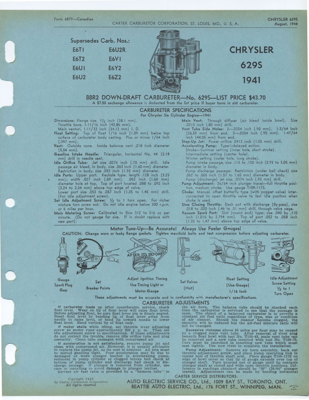
BBR2 DOWN-DRAFT CARBURETER—No. 629S—LIST PRICE $43.70
A $7.50 exchange allowance is deducted from the list price if buyer turns in
old carbureter.
CARBURETER SPECIFICATIONS
For Chrysler Six Cylinder Engine—1941
Dimensions: Flange size, 11/2 inch (38.1 mm).
Throttle bore, I-II/16 inch (42.86 mm).
Main venturi, I-I I/32 inch (34.13 mm) I. D.
Float Setting: Top of float 1/16 inch (1.59 mm) below top surface of carbureter
body casting. Plus or minus 1/64 inch (.397 mm).
Vent: Outside none. Inside balance vent .218 inch diameter (5.54 mm).
Gasoline Intake Needle: Triangular, horizontal No. 44 (2.18 mm) drill in needle
seat.
Idle Orifice Tube: Jet size .0276 inch (.70 mm) drill. Idle passage air bleed,
in body, size .063 inch (1.60 mm) diameter. Restriction in body, size .053
inch (1.35 mm) diameter.
Idle Ports: Upper port. Keyhole type: length .128 inch (3.25 mm); width .027
inch (.69 mm). .063 inch (1.60 mm) diameter hole at top. Top of port located
.088 to .092 inch (2.24 to 2.34 mm) above top edge of valve.
Lower port size .053 to .057 inch (1.35 to 1.45 mm) drill. (For idle adjustment
screw).
Set Idle Adjustment Screw: 1/2 to I turn open. For richer mixture turn screw
out. Do not idle engine below 300 r.p.m. or 6 miles per hour.
Main Metering Screw: Calibrated to flow 312 to 316 cc per minute. (Do not gauge
for size. If in doubt replace with new part).
Main Vent: Through diffuser (air bleed inside bowl). Size .0315 inch (.80 mm)
drill.
Vent Tube Side Holes: 2—.0354 inch (.90 mm). 1-3/64 inch (26.59 mm) from
end. 2—.0354 inch (.90 mm). 1-47/64 inch (44.05 mm) from end.
Step-Up Jet: Power orifice .0413 inch (1.05 mm) drill. Accelerating Pump: Type:
delayed action.
Stroke—Summer setting (inner hole, short stroke). Intermediate setting
(center hole).
Winter setting (outer hole, long stroke).
Pump intake passage, size .115 to .120 inch (2.93 to 3.05 mm) diameter in body.
Pump discharge passage: Restriction (under ball check) size .062 to .065 inch
(1.57 to 1.65 mm) diameter in body. Pump (discharge) jet size, .0374 inch (.95
mm) drill.
Pump Adjustment: 26/64 inch plunger travel—full throttle position, medium
stroke. Use gauge T109-1175.
Choke: Manual, offset butterfly type (with poppet valve) inter-connected to
open throttle valve to fast idle position when choke is used.
Slow Closing Throttle: Dash pot with discharge (By-pass), size
.018 to .020 inch (.46 to .51 mm) drill, through valve cage.
Vacuum Spark Port: Slot (round end) type; size .040 by .110 inch (1.016 by
2.794 mm). Top of port .052 to .058 inch (1.32 to 1.47 mm) above top edge of
valve.
Motor Tune-Up—Be Accurate! Always Use Feeler Gauges!
CAUTION: Change worn or leaky flange gaskets. Tighten manifold bolts and test
compression before adjusting carbureter.
Float Setting (Use Gauge) 1/16 Inch These adjustments must be accurate and
in conformity with manufacturer's specifications.
CARBURETER ADJUSTMENTS
Gauge
Spark Plug
Gap
Set
Breaker Points
Adjust Ignition Timing
Use Timing Light or
Motor Gauge
Set Valves
(Hot)
Idle Adjustment
Screw Setting
Y2 to I
Turn Open
If carbureter loads up after considerable service, check float level. Wear
on lip of float lever will raise float level. Before adjusting float, be sure
float lever pin is firmly seated. Reset float level by bending lip of float
lever away from needle to raise level, or bend lip toward needle to lower float
level. Bend vertical lip of float only.
If motor stalls while idling, set throttle lever adjusting screw so motor runs
approximately 300 r. p. m. Then set idle adjustment screw to specifications.
If these adjustments do not correct the trouble, remove idle orifice tube and
plug assembly. Clean tube passages with compressed air.
If acceleration is not satisfactory, remove pump jet and clean with compressed
air. However, it is usually advisable to replace the pump jet, as its cost
is nominal. All jets must be seated gasoline tight. Poor acceleration may be
due to damaged or worn plunger leather in accelerating pump, sediment in pump
cylinder or clogged intake ball check at bottom of pump cylinder and discharge
ball check in discharge passage. If plunger is removed from cylinder, use care
un installing to avoid damage to plunger leather.
Correct air fuel ratio is provided by a "balance tube" in
the air horn. The balance tube should be checked each time the carbureter is
serviced to see that the passage Is open. The object of a balanced carbureter
is to provide a constant air fuel ratio regardless of type, size or condition
of air cleaner. Should the cleaner become clogged, the capacity will be reduced
but the air-fuel mixture ratio will not be changed.
Excessive richness above 50 miles per hour may be caused by a clogged main
vent tube. After removal of rivet plug beneath float bowl with tool No. T109-43,
main vent tube can be removed and a new tube inserted with tool No. T109-70.
Care must be exercised in inserting new tube which must seat tightly. Use new
rivet to complete the installation.
Pump Adjustment: Remove air horn assembly, back out throttle adjustment screw,
and place pump operating link in center hole of throttle shaft arm. Place gauge
T109-117S on edge of bowl cover so that lip of gauge extends over top of plunger
shaft. Turn knurled nut of gauge until lip contacts plunger shaft at closed
and wide open throttle positions. Difference in readings obtained should be "26" (26/64" plunger
travel). Adjustments can be made by bending horizontal