Chrysler Old Carter Carburetors : CHRYSLER 629S 1941Previous | Home | Next |
 |
portion of pump connector link.
Pump stroke adjustable for high or low temperature. Set to long stroke for
cold weather, short stroke for hot weather driving.
NOTE:
In replacing a carbureter having a screw adjusted dash pot with one having
the electric magnet dash pot, the electricalconnections should be made as follows:
1. Connect either one of the solenoid terminals with the terminal on the kickdown
limit switch on the carbureter.
2. Connect the other solenoid terminal to the point marked SF (solenoid feed)
on the relay Chrysler' part No. 868606, situated at the right of the voltage
regulator. The relay terminal marked SF already carries two wires and will
then have three wires connected.
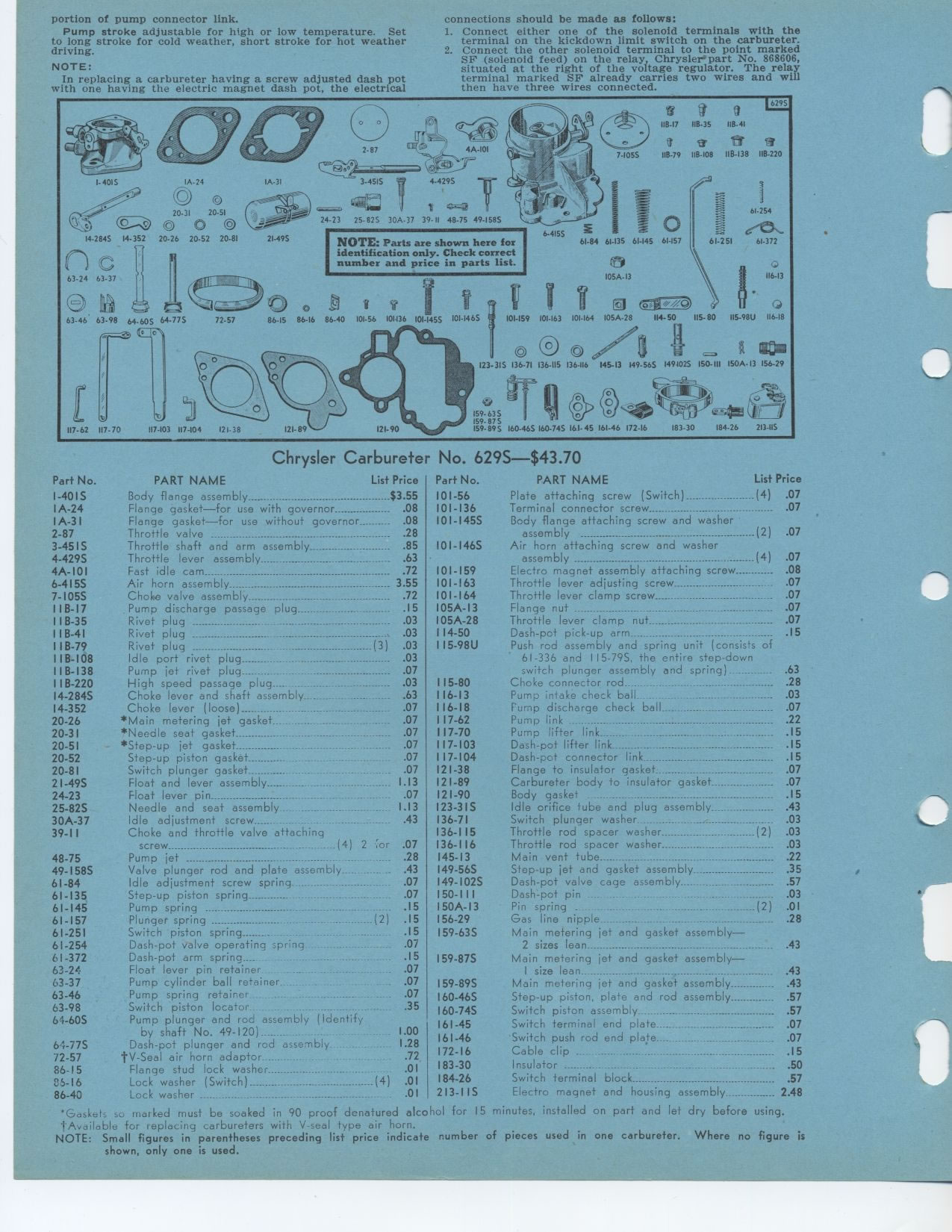
Chrysler Carbureter No. 629S-$43.70
Part No. PART NAME List Price Part No. PART NAME List Price
I-401S Body flange assembly $3.55 101-56
IA-24 Flange gasket—for use with governor 08 101-136
IA-3I Flange gasket—for use without governor-- 08 101-1455
2-87 Throttle valve 28
3-451S Throttle shaft and arm assembly 85 I01-146S
4-429S Throttle lever assembly 63
4A-10I Fast idle cam 72 101-159
6-415S Air horn assembly._--_ 3 55 101-163
7-105S Choke valve assembly 72 101-164
I B-17 Pump discharge passage plug 15 105A-13
118-35 Rivet plug 03 105A-28
I B-41 Rivet plug .03 114-50
1IB-79 Rivet plug _ (3) 03 I15-98U
I 1 B-108 Idle port rivet plug 03
IIB-138 Pump jet rivet plug 07
IIB-220 High speed passage plug -_ 03 115-80
14-2845 Choke lever and shaft assembly. .-__. - .63 116-13
14-352 Choke lever (loose) - .07 116-18
20-26 *Main metering jet gasket._-. _._.. .-__- .07 117-62
20-3 I *Needle seat gasket 07 117-70
20-51 *Step-up jet gasket - -__ _ .07 117-103
20-52 Step-up piston gasket 07 117-104
20-81 Switch plunger gasket - 07 121-38
21-49S Float and lever assembly _- 1.13 121-89
24-23 Float lever pin - .07 121-90
25-82S Needle and seat assembly ._.___.-.... 1.13 123-31S
30A-37 Idle adjustment screw 43 136-71
39-I1 Choke and throttle valve attachinq 136-I15
screw (4) 2 Gor 07 136-116
48-75 Pump jet -- .28 145-13
49-158S Valve plunger rod and plate assembly . . .43 149-56S
61-84 Idle adjustment screw spring 07 149-102S
61-135 Step-up piston spring 07 150-III
61-145 Pump spring _ 15 150A-13
61-157 Plunger spring ---__ (2) 15 156-29
61-251 Switch piston spring 15 159.63S
61-254 Dash-pot valve operating spring 07
61-372 Dash-pot arm spring.... .15 159-87S
63-24 Float lever pin retainer 07
63-37 Pump cylinder ball retainer... .07
63-46 Pump spring retainer_ 07
63-98 Switch piston locator _ 35
64-60S Pump plunger and rod assembly (Identify
by shaft No. 49-120) .. 1.00
64-77S Dash-pot plunger and rod assembly 1.28
72-57 tV-Seal air horn adaptor .._ .72
86-15 Flange stud lock washer 01
85-16 Lock washer (Switch) (4) .01
86-40 Lock washer -_ 01
Plate attaching screw (Switch) (4)
Terminal connector screw
Body flange attaching screw and washer
assembly (2)
Air horn attaching screw and washer
assembly (4) 07
Electro magnet assembly attaching screw 08
Throttle lever adjusting screw 07
Throttle lever clamp screw 07
Flange nut ... .... . . .07
Throttle lever clamp nut- 07
Dash-pot pick-up arm ...... .I5
Push rod assembly and spring unit (consists of 61-336 and 115-79S, the entire
step-down
switch plunger assembly and spring) 63
Choke connector rod 28
Pump intake check ball- ..... 03
Fump discharge check ball 07
Pump link -22
Pump lifter link .15
Dash-pot lifter link 15
Dash-pot connector link 15
Flange to insulator gasket 07
Carbureter body to insulator gasket 07
Body gasket - ..... -15
Idle orifice tube and plug assembly 43
Switch plunger washer- 03
Throttle rod spacer washer (2) 03
Throttle rod spacer washer 03
Main vent tube 22
Step-up jet and gasket assembly 35
Dash-pot valve cage assembly .... 57
Dash-pot pin 03
Pin spring (2) 01
Gas line nipple ......... 28
Main metering jet and gasket assembly
2 sizes lean
Main metering jet and gasket assembly
I size lean ......---- .43
Main metering jet and gasket assembly _ .43
Step-up piston, plate and rod assembly 57
Switch piston assembly 57
Switch terminal end plate ..... 07
Switch push rod end plate 07
Cable clip . . ...... .15
Insulator .-.--...--_._.-.. __ 50
Switch terminal block.__ .. 57
Electro magnet and housing assembly 2 48
'Gasket. se marked must be soaked in 90 proof denatured alcohol for 15 minutes,
installed on part and let dry before using. 1 Available for replacing carburetors
with V-seal type air horn.
NOTE: Small figures in parentheses preceding list price indicate number of
pieces used in one carbureter. Where no figure is shown, only one is used.