Chrysler Old Carter Carburetors : CHRYSLER 8 MODELS C39 C40 FLUID DRIVE & VACAMATIC TRANSMISSION 1946Previous | Home | Next |
 |
Poor acceleration may be due to damaged or worn plunger leather in accelerating
pump or pump check balls not seating properly. If plunger is removed from
cylinder, use care when installing to avoid damage to plunger leather.
Correct air fuel ratio is provided by a "balance tube" in the air
horn. The "balance tube" and vent passage must not be restricted.
The object of a balanced carbureter is to provide a constant air fuel ratio
regardless of type, size or condition of air cleaner. Should the cleaner become
clogged, the capacity will be reduced but the air-fuel mixture ratio will not
be changed.
Excessive richness above 50 miles per hour may he caused by a clogged main
vent tube. After removal of rivet plug beneath float bowl with tool No. T109-42,
main vent tube can be removed and a new tube inserted with tool No. T109-70.
Care must be exercised in inserting new tube which mustseat tightly. Use new
rivet to complete the installation.
Pump Adjustment: Remove air horn assembly, back out throttle lever adjustment
screw, and locate pump link in center hole of throttle shaft arm. Place universal
pump travel gauge T109-117S on edge of bowl su that lip of gaugt extends over
top of plunger shaft. Turn knurled nut of gaup, until lip contacts top of plunger
shaft at closed throttle position. Take reading indicated on gauge. Repeat
with throttle wide open. Difference in readings obtained should be "26" (26/64" plunger
travel). Adjustment may be made by bending horizontal portion of pump lifter
link.
Seasonal Pump Adjustment: Three holes are provided in pump arm to meet seasonal
or climatic conditions. For high altitudes or extreme heat, use short stroke
(inner hole); win-ter setting: long stroke (outer hole) or intermediate stroke
(center hole).
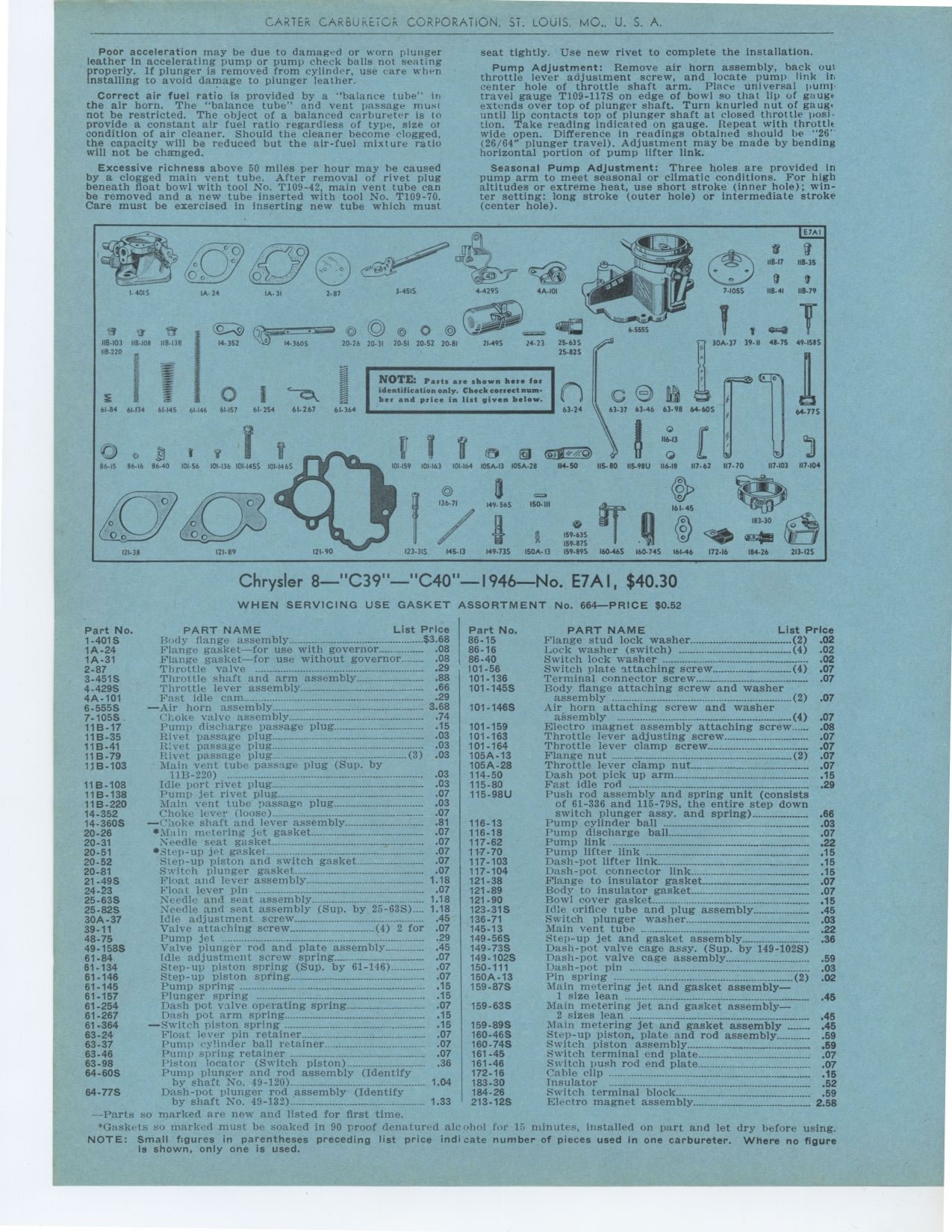
WHEN SERVICING USE GASKET ASSORTMENT No. 664—PRICE $0.52
Part No. PART NAME List Price
1-401S Rudy flange assembly $3 68
1A-24 Flange gasket—for use with governor 08
1A-31 Flange gasket—for use without governor 08
2-87 Throttle valve 29
3-451S Throttle shaft and arm assembly 88
4-429S Throttle lever assembly 66
4A-101 Fast idle cam..- 29
6-555S —Air horn assembly 3 68
7-105S Choke valve assembly 74
11B-17 Pump discharge passage plug 15
11B-35 Rivet passage plug 03
11B-41 Rivet passage plug 03
11 B-79 Rivet passage plug plug (3) 03
11B-103 Main vent tube passage plug (Sup. by
11B-220) -° 03
11B-108 Idle port rivet plug -° 03
11B-138 Pump jet rivet plug 07
11B-220 Main vent tube passage plug 03
14-352 Choke lever (loose) 07
14-360S —Choke shaft and lever assembly 81
20-26 *Main metering jet gasket 07
20-31 Needle seat gasket 07
20-51 •Step-up jet gasket 07
20-52 Step-up piston and switch gasket 07
20-81 Switch plunger gasket 07
21-49S Float and lever assembly 1 18
24-23 Float lever pin
-07 25-63S Needle and seat assembly 1 18
25-82S Needle and seat assembly (Sup. by 25-63S)._- 1 18
30A-37 Idle adjustment screw 45
39-11 Valve attaching screw (4) 2 for 07
48-75 Pump jet -°- 29
49-158S Valve plunger rod and plate assembly 45
61-84 Idle adjustment screw spring 07
61-134 Step-up piston spring (Sup. by 61-146) 07
61-146 Step-up piston spring 07
61-145 Pump spring -----° 15
61-157 Plunger spring 15
61-254 Dash pot valve operating spring 07
61.267 Dash pot arm spring 15
61-364 —Switch piston spring 15
63-24 Float lever pin retainer 07
63-37 Pump cylinder ball retainer _ .07
63-46 Pump spring retainer 07
63-98 Piston locator (Switch piston) 36
64-60S Pump plunger and rod assembly (Identify
by shaft No. 49-120) 1 04
64-77S Dash-pot plunger rod assembly (Identify
by shaft No. 49-132) 1 33
—Parts so marked are new and listed for first time.
PART NAME List Price
Flange stud lock washer (2) .02
Lock washer (switch) (4) .02
Switch lock washer 02
Switch plate attaching screw (4) .07
Terminal connector screw : 07
Body flange attaching screw and washer
assembly (2) 07
Air horn attaching screw and washer
assembly ° ----°-°---°---°----...°--(4) 07
Electro magnet assembly attaching screw 08
Throttle lever adjusting screw 07
Throttle lever clamp screw 07
Flange nut (2) 07
Throttle lever clamp nut 07
Dash pot pick up arm .°° 15
Fast idle rod °---- 29
Push rod assembly and spring unit (consists of 61-336 and 115-79S, the entire
step down
switch plunger assy. and spring) 66
Pump cylinder ball 03
Pump discharge ball 07
Pump link 22
Pump lifter link 15
Dash-pot lifter link 15
Bash-pot connector link 15
Flange to insulator gasket 07
Body to insulator gasket 07
Bowl cover gasket 15
Idle orifice tube and plug assembly 45
Switch plunger washer 03
Main vent tube 22
Step-up jet and gasket assembly 36
Dash-pot valve cage assy. (Sup. by 149-102S)
Dash-pot valve cage assembly 59
Dash-pot pin 03
Pin spring .. .........-°----°-- (2) .02
Main metering jet and gasket assembly
] size lean -°- ---° 45
Main metering jet and gasket assembly
2 sizes lean ° 45
Main metering jet and gasket assembly 45
Step-up piston, plate and rod assembly 59
Switch piston assembly 59
Switch terminal end plate 07
Switch push rod end plate 07
Cable clip -----°-° 15
insulator °°....°° ---° 52
Switch terminal block 59
Eleetro magnet assembly 2 58
"Gaskets so marked must be soaked in 90 proof denatured alcohol NOTE: Small
figures in parentheses preceding list price indicate is shown, only one is used.
he. It, minutes, installed on part and let dry before using. number of pieces
used in one carbureter. Where no figure