Chrysler Old Carter Carburetors : CHRYSLER MODEL C34 1942Previous | Home | Next |
 |
be removed and a new tube inserted with tool No. T109-70. Care
must be exercised in inserting new tube which must seat tightly. Use new rivet
to complete the installation.
Pump Adjustment: Remove air horn assembly, back out throttle adjustment screw,
and place pump operating link in center hole of throttle shaft arm. Adjustment
can be made by bending horizontal portion of pump connector link, so that top
of pump plunger shaft contacts lip of indicator on pump stroke gauge T109-117S.
Correct travel is 26/64".
Pump stroke adjustable for high or low temperature. Set to longest stroke for
cold weather, shorter stroke for hot weather driving.
DASH-POT (EF1): Motors operating in connection with fluid couplings tend to
stall under rapid decelerating conditions unless the throttle is made to close
slowly. Slow throttle movement is necessary only the last part of the closing.
The dash-pot or decelerating pump acts as a snubber to the throttle, allowing
fast movement to almost closed position, then slow closing from that point
to the idle position.
Dash-pot operation is as follows: As the throttle is opened linkage raises
the plunger, filling the dash-pot cylinder with gasoline from the bowl. There
is little or no resistance to the gasoline as the cylinder fills. However,
when the throttle is released, the throttle valve closes rapidly until throttle
arm contacts dash-pot plunger arm. Then the plunger must be pushed to the bottom
of the cylinder before the throttle can close. A ball check located in the
lower end of the plunger shaft, seals the large upper openings and the gasoline
must leave the cylinder through the small metered hole in lower end of the
shaft. This reduces the rate at which plunger can be forced to the bottom of
the cylinder making the last part of throttle closing very slow. The adjusting
screw (in top of bowl cover) should be opened five full turns, from closed
position for average conditions. Under extreme driving conditions greater openings
may be necessary, al-though extreme dash-pot action will effect gear change
and not enough action will cause engine to stall.
lt.• sure plunger leather is soft and pliable and effects a gi.od seal
against the cylinder wall.
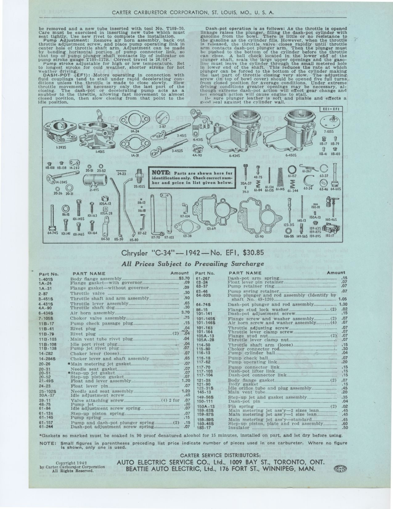
NOTE: Parts are shown here for identification only. Check correct number and
price in list given below.
8
Le'‘
Chrysler "C-34"-1942-No. EFI, $30.85 All Prices Subject to Prevailing
Surcharge
Part No. PART NAME Amount Part No.
1-401S Body flange assembly $3 70 61.267
1A-24 Flange gasket—with governor 09 63-24
1A-31 Flange gasket—without governor 09 63-37
2-87 Throttle valve 30
3-451S Throttle shaft and arm assembly 90
4-431S Throttle lever assembly 65 64-74S
4A-90 Throttle shaft dog 30 86-15
6-434S Air horn assembly 3 70 101.141
7.105S Choker valve assembly 75 101-145S
11B-17 Pump check passage plug 15 101-146S
11B-41 Rivet plug 04
11B-79 Rivet plug (2) 04
11B-103 Main vent tube rivet plug 04
11B-108 Idle port rivet plug 04 114-50
11B-138 Pump jet rivet plug 07 115-80
14-282 Choker lever (loose) : 07 116-13
14-284S Choker lever and shaft assembly 65
20-26 •Main metering jet gasket 07
20-31 Needle seat gasket 07
20.51 •Step-up jet gasket___ 07
20-52 Step-up piston gasket 07
21-49S Float and lever assembly 1 20
24-23 Float lever pin 07
25-102S Needle and seat assembly 1 20
30A-37 Idle adjustment screw : 45
39-11 Valve attaching screw (4) 2 for 07
48.75 Pump jet --- °---- 30
61-84 Idle adjustment screw spring 07
61-134 Step-up piston spring 07
61.145 Pump spring 15
61-157 Pump and dash-pot plunger spring (2) .15
61-244 Dash-pot adjustment screw spring ..: 07
PART NAME Amount
Dash-pot arm spring 15
Float lever pin retainer 07
Pump retainer ring 07
Pump snring retainer 07
Pump plunger and rod assembly (Identify by
shaft No. 49-120) 1 05
Dash-pot plunger and rod assembly 1 30
Flange stud lock washer (2) 02
Dash-pot adjustment screw 15
Flange screw and washer assembly (2) 07
Air horn screw and washer assembly (4) 07
Throttle adjusting screw 07
Throttle lever clamp screw 07
Flange stud nut (2) .07
Throttle lever clamp nut : 07
Throttle shaft arm (loose) 15
Choker connector rod : 30
Pump cylinder ball 04
Pump check ball 07
Pump operating link 20
Pump connector link 15
Dash-pot lifter link 15
Dash-pot connector link 15
Body flange gasket (2) 07
Body gasket 15
Idle orifice tube and plug assembly 45
Main vent tube 20
Step-up jet and gasket assembly 35
Dash-pot pin 04
Pin spring (2) 02
Main metering jet ass'y—2 sizes lean 45
Main metering jet ass'y—1 size lean 45
Main metering jet ass'y—standard 45
Step-up piston, plate and rod assembly 60
Insulator -°----° ° 50
63.46 64.60S
101-163 101-164 105A-13 105A-28
116-18 117-62 117-70 117-103 117-104
121-38 121-90 123-31S 145.13
149-56S 150-111 150A-13 159-63S 159.87S
159.89S 160-46S 183-17
'Gaskets so marked must be soaked in 90 proof denatured alcohol for 15 minutes,
installed on part, and let dry before using.
NOTE: Small figures in parentheses preceding list price indicate number of
pieces used in one carbureter. Where no figure Is shown, only one is used.
Copyright 1942