|
Page 2
CARBURETER
If carbureter loads up after considerable service, check float level. Wear
on lip of float lever will raise float level. Before adjusting float, be
sure float lever pin is firmly seated. Reset float level by bending lip of
float lever away from needle to raise level, or bend lip toward needle to
lower float level. Bend vertical lip of float only.
If motor stalls while idling, set throttle lever adjusting screw so motor
runs approximately 300 r. p. m. Then set idle adjustment screw to specifications.
If these adjustments do not correct the trouble, remove idle orifice tube
and plug assembly. Clean tube and passages with compressed air.
If acceleration is not satisfactory remove pump jet and clean with compressed
air. However, it is usual)y advisable to replace the pump jet, as its cost
is nominal. All jets must be seated gasoline tight. Poor acceleration may
be due to damaged or worn plunger leather in accelerating pump, sediment
in pump cylinder or clogged intake ball check at bottom of pump cylinder
and discharge ball check in discharge passage. If plunger is removed from
cylinder, use care in installing to avoid damage to plunger leather.
Correct air fuel ratio is provided by a "balance tube" cast in
the air horn. The balance tube should be checked each time the carbureter
is serviced to see that the passage is open. The object of a balanced carbureter
is' to provide a constant air fuel ratio regardless of type, size or condition
of air cleaner. Should the cleaner become clogged, the capacity will be reduced
but the air-fuel mixture ratio will not be changed.
Excessive richness above 50 miles per hour may be caused by a clogged main
vent tube. After removal
ADJUSTMENTS
of rivet plug beneath float bowl with tool No. T109-42, main vent tube can
be removed and a new tube inserted with tool No. T I09-70. Care must be exercised
in inserting new tube which must seat tightly. Use new rivet to complete
the installation.
Pump Adjustment: Remove air horn assembly, back out throttle adjustment screw,
and place pump operating link in center hole of throttle shaft arm. Adjustment
can be made by bending horizontal portion of pump connector link, so that
top of pump plunger shaft contacts lip of indicator on pump stroke gauge
TI 09- 117S. Correct travel is 13/32".
Pump stroke adjustable for high or low temperature. Set to longest stroke
for cold weather, shorter stroke for hot weather driving.
Maximum economy and performance are secured only when breaker points, spark
plugs, valves and motor timing are set to manufacturer's specifications.
After motor is properly tuned, the' following should also be done to insure
satisfactory performance and economy:
(a) Float level must be set as above.
(b) Step-up rod in step-up jet must seat and move freely. When reassembling,
jet must be screwed in tight against seat.
(c) Step-up piston in body casting should not bind and must be free of dirt.
(d) Main metering jet can be replaced with leaner than standard metering
jets, for altitude or high test fuel.
Caution: Do not attempt to gauge metering jets with drills. These jets have
been flow-tested to insure correct fuel flow.
SPECIAL ADJUSTMENTS
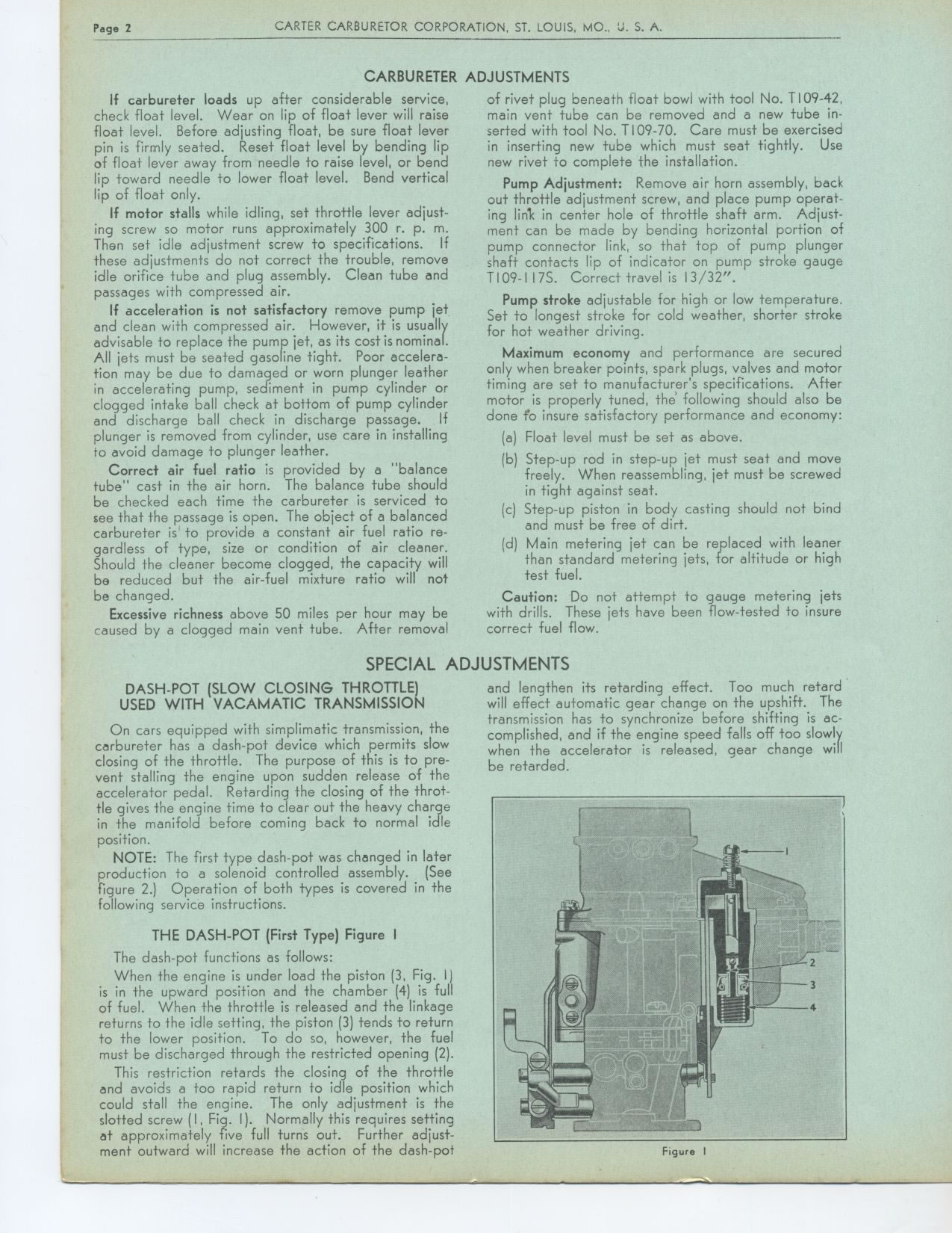
DASH-POT (SLOW CLOSING THROTTLE) and lengthen its retarding effect. Too much
retard
USED WITH VACAMATIC TRANSMISSION will effect automatic gear change on the
upshift. The transmission has to synchronize before shifting is accomplished,
and if the engine speed falls off too slowly when the accelerator is released,
gear change will be retarded.
On cars equipped with simplimatic transmission, the carbureter has a dash-pot
device which permits slow closing of the throttle. The purpose of this is
to pre-vent stalling the engine upon sudden release of the accelerator pedal.
Retarding the closing of the throttle gives the engine time to clear out
the heavy charge in the manifold before coming back to normal idle position.
NOTE: The first type dash-pot was changed in later production to a solenoid
controlled assembly. (See figure 2.) Operation of both types is covered in
the following service instructions.
THE DASH-POT (First Type) Figure I
The dash-pot functions as follows:
When the engine is under load the piston (3, Fig. II is in the upward position
and the chamber (4) is full of fuel. When the throttle is released and the
linkage returns to the idle setting, the piston (3) tends to return to the
lower position. To do so, however, the fuel must be discharged through the
restricted opening (2).
This restriction retards the closing of the throttle and avoids a too rapid
return to idle position which could stall the engine. The only adjustment
is the slotted screw (I, Fig. I). Normally this requires setting at approximately
five full turns out. Further adjustment outward will increase the action
of the dash-pot
Figure I
|