Chrysler Old Carter Carburetors : CHRYSLER MODEL C28 Fluid Drive & Vacamatic Transmission 1941Previous | Home | Next |
 |
Page 3
The leather seal on piston (3, Fig. I) controls the retarding action. Should
this seal become worn, cracked or dry, the action will be upset. A good seal
is necessary for the control to function properly.
DASH-POT (Second Type) Figure 2
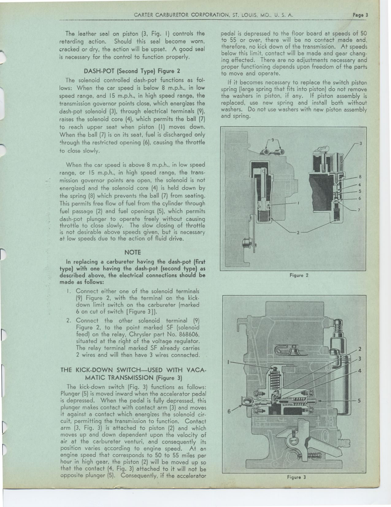
The solenoid controlled dash-pot functions as follows: When the car speed is
below 8 m.p.h., in low speed range, and 15 m.p.h., in high speed range, the
transmission governor points close, which energizes the dash-pot solenoid (3),
through electrical terminals (9), raises the solenoid core (4), which permits
the ball (7) to reach upper seat when piston (I) moves down. When the ball
(7) is on its seat, fuel is discharged only through the restricted opening
(6), causing the throttle
to close slowly.
When the car speed is above 8 m.p.h., in low speed range, or 15 m.p.h., in
high speed range, the trans-mission governor points are open, the solenoid
is not energized and the solenoid core (4) is held down by the spring (8) which
prevents the ball (7) from seating. This permits free flow of fuel from the
cylinder through fuel passage (2) and fuel openings (5), which permits dash-pot
plunger to operate freely without causing
throttle to close slowly. The slow closing of throttle is not desirable above
speeds given, but is necessary at low speeds due to the action of fluid drive.
NOTE
In replacing a carbureter having the dash-pot (first type) with one having
the dash-pot (second type) as described above, the electrical connections should
be made as follows:
I. Connect either one of the solenoid terminals (9) Figure 2, with the terminal
on the kick-down limit switch on the carbureter (marked 6 on cut of switch
[Figure 3]).
2. Connect the other solenoid terminal (9) Figure 2, to the point marked SF
(solenoid feed) on the relay, Chrysler part No. 868606, situated at the right
of the voltage regulator. The relay terminal marked SF already carries 2 wires
and will then have 3 wires connected.
THE KICK-DOWN SWITCH—USED WITH VACA-
MATIC TRANSMISSION (Figure 3)
The kick-down switch (Fig. 3) functions as follows: Plunger (5) is moved inward
when the accelerator pedal is depressed. When the pedal is fully depressed,
this plunger makes contact with contact arm (3) and moves it against a contact
which energizes the solenoid circuit, permitting the transmission to function.
Contact arm (3, Fig. 3) is attached to piston (2) and which moves up and down
dependent upon the velocity of air at the carbureter venturi, and consequently
its position varies according to engine speed. At an engine speed that corresponds
to 50 to 55 miles per hour in high gear, the piston (2) will be moved up so
that the contact (4, Fig. 3) attached to it will not be opposite plunger (5).
Consequently, if the acceleratorpedal is depressed to the floor board at speeds
of 50 to 55 or over, there will be no contact made and, therefore, no kick
down of the transmission. At speeds below this limit, contact will be made
and gear changing effected. There are no adjustments necessary and proper functioning
depends upon freedom of the parts to move and operate.
If it becomes necessary to replace the switch piston spring (large spring that
fits into piston) do not remove the washers in piston, if any. If piston assembly
is replaced, use new spring and install both without washers. Do not use washers
with new piston assembly and spring.
Figure 2
Figure 3