Chrysler Old Carter Carburetors : CANADIAN CHRYSLER MODEL CA 1934Previous | Home | Next |
 |
Form 6113C—Canadian
CHRYSLER E6CI
March, 1934
Reprinted July, 1944
CAR SERIAL NUMBERS "CA" 9702226 and higher
MOTOR SERIAL NUMBERS
CA-100I and higher
CANADIAN
CHRYSLER
MODEL CA
1934
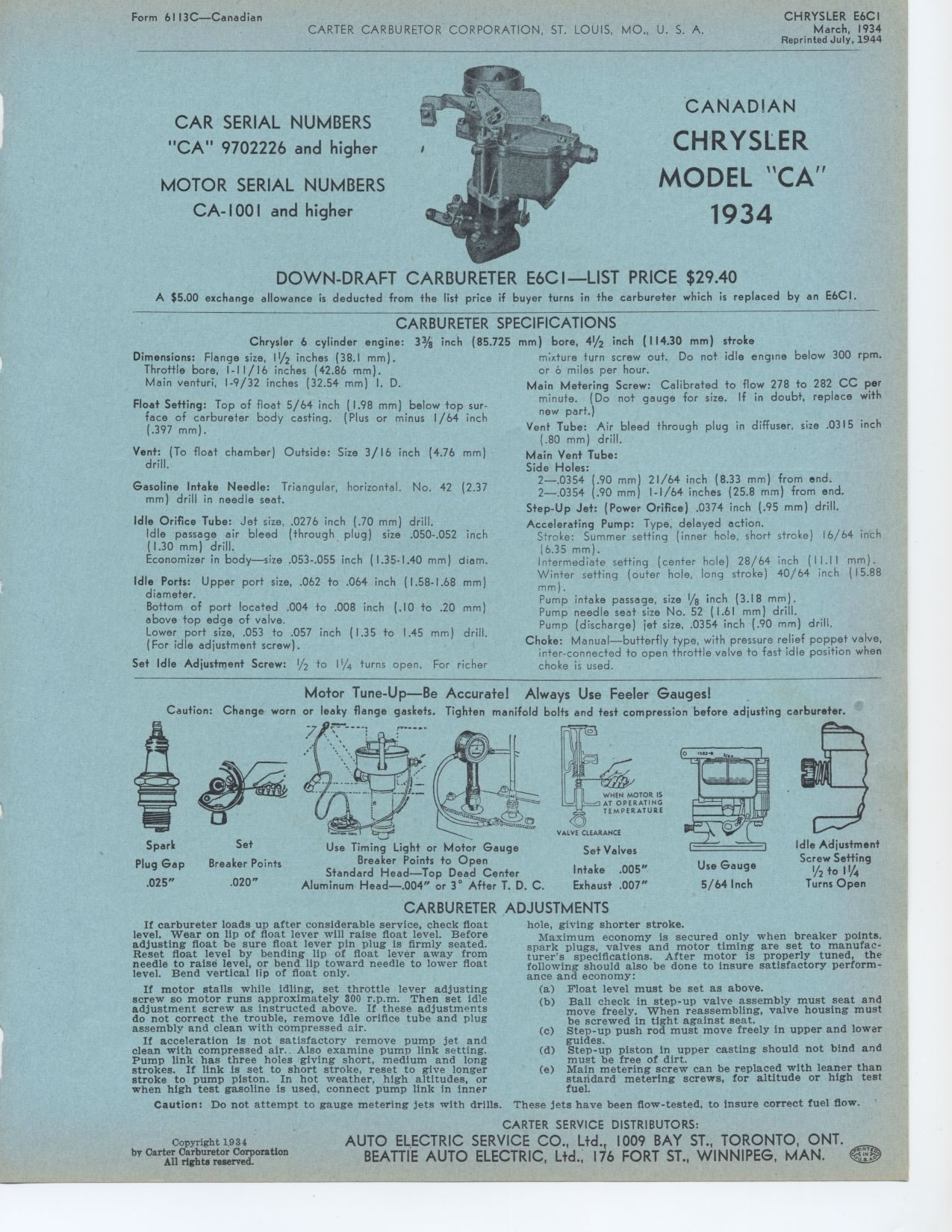
DOWN-DRAFT CARBURETER E6CI—LIST PRICE $29.40
A $5.00 exchange allowance is deducted from the list price if buyer turns in
the carbureter which is replaced by an E6CI.
CARBURETER SPECIFICATIONS
(85.725 mm) bore, 41/2 inch (114.30 mm) stroke
mixture turn screw out. Do not idle engine below 300 rpm. or 6 miles per hour.
Main Metering Screw: Calibrated to flow 278 to 282 CC per minute. (Do not gauge
for size. If in doubt, replace with new part.)
Vent Tube: Air bleed through plug in diffuser, size .0315 inch (.80 mm) drill.
Main Vent Tube:
Side Holes:
2—.0354 (.90 mm) 21/64 inch (8.33 mm) from end. 2—.0354 (.90 mm)
I-1/64 inches (25.8 mm) from end. Step-Up Jet: (Power Orifice) .0374 inch (.95
mm) drill.
Accelerating Pump: Type, delayed action.
Stroke: Summer setting (inner hole, short stroke) 16/64 inch (6.35 mm).
Intermediate setting (center hole) 28/64 inch (11.11 mm). Winter setting (outer
hole, long stroke) 40/64 inch (15.88 mm).
Pump intake passage, size 1/8 inch (3.18 mm).
Pump needle seat size No. 52 (1.61 mm) drill.
Pump (discharge) jet size, .0354 inch (.90 mm) drill.
Choke: Manual—butterfly type, with pressure relief poppet valve, inter-connected
to open throttle valve to fast idle position when choke is used.
Motor Tune-Up—Be Accurate! Always Use Feeler Gauges! .
Caution: Change worn or leaky flange gaskets. Tighten manifold bolts and test
compression before adjusting carbureter.
Chrysler 6 cylinder engine: 33/8 inch Dimensions: Flange size, 11/2 inches
(38.1 mm).
Throttle bore, I-11/16 inches (42.86 mm).
Main venturi, 1-9/32 inches (32.54 mm) I. D.
Float Setting: Top of float 5/64 inch (1.98 mm) below top surface of carbureter
body casting. (Plus or minus 1/64 inch (.397 mm).
Vent: (To float chamber) Outside: drill.
Size 3/16 inch (4.76 mm)
Gasoline Intake Needle: Triangular, horizontal. No. 42 (2.37 mm) drill in needle
seat.
Idle Orifice Tube: Jet size, .0276 inch (.70 mm) drill. Idle passage air bleed
(through plug) (1.30 mm) drill.
Economizer in body—size .053-.055 inch (1.35-1.40
Idle Ports: Upper port size, .062 to .064 inch (1.58-1.68 mm) diameter.
Bottom of port located .004 to .008 inch (.10 to .20 mm) above top edge of
valve.
Lower port size, .053 to .057 inch (1.35 to 1.45 mm) drill. (For idle adjustment
screw).
Set Idle Adjustment Screw: 1/2 to 11/4 turns open. For richer
size .050-.052 inch
mm) diem.
CARBURETER ADJUSTMENTS
Idle Adjustment
Screw Setting
l/2 to 1 l/4
Turns Open
Spark Set
Plug Gap Breaker Points
.025" .020"
Use Timing Light or Motor Gauge
Breaker Points to Open
Standard Head—Top Dead Center
Aluminum Head—.004" or 3° After T. D. C.
VALVE CLEARANCE
Set Valves
Intake .005" Exhaust .007"
Use Gauge 5/64 Inch
If carbureter loads up after considerable service, check float level. Wear
on lip of float lever will raise float level. Before adjusting float be sure
float lever pin plug is firmly seated. Reset float level by bending lip of
float lever away from needle to raise level, or bend lip toward needle to lower
float level. Bend vertical lip of float only.
If motor stalls while idling, set throttle lever adjusting screw so motor runs
approximately 300 r.p.m. Then set idle adjustment screw as instructed above.
If these adjustments do not correct the trouble, remove idle orifice tube and
plug assembly and clean with compressed air.
If acceleration is not satisfactory remove pump jet and clean with compressed
air. Also examine pump link setting. Pump link has three holes giving short,
medium and long strokes. If link is set to short stroke, reset to give longer
stroke to pump piston. In hot weather, high altitudes, or when high test gasoline
is used, connect pump link in innerhole, giving shorter stroke.
Maximum economy is secured only when breaker points, spark plugs, valves and
motor timing are set to manufacturer's specifications. After motor is properly
tuned, the following should also be done to insure satisfactory performance
and economy:
(a) Float level must be set as above.
(b) Ball check in step-up valve assembly must seat and move freely. When reassembling,
valve housing must be screwed in tight against seat.
(c) Step-up push rod must move freely in upper and lower guides.
(d) Step-up piston in upper casting should not bind and must be free of dirt.
(e) Main metering screw can be replaced with leaner than standard metering
screws, for altitude or high test fuel.
Caution: Do not attempt to gauge metering jets with drills. These jets have
been flow-tested, to insure correct fuel flow.
Copyright 1934