Carburetors for old Dodge Trucks : CARTER VELOCITY GOVERNORPrevious | Home | Next |
 |
Page
3
GOVERNOR SERVICE INSTRUCTIONS
If governor has been tampered with, or should the adjusting screw be turned
out of the primary spring due to faulty adjustment, recalibration will be necessary
to insure proper operation. This will require removal of the carbureter from
the engine. If recalibration is necessary, proceed as follows:
1. Determine the governor unit number (stamped on the cover plate and also
on housing on later production) and refer to the chart in conjunction with
Figure 2 for calibration specifications.
2. Remove lead seal plugs from the two depressed screw openings in the governor
cover plate by prying out with a small screw driver. Remove .all retaining
screws and cover. Never attempt to remove governing lever assembly from end
of throttle valve shaft.
3. Remove shaft housing and lever assembly located at end of throttle shaft
opposite governor assembly. Before removal be sure to note and mark position
of long throttle stop screw for correct reassembly. Never immerse this part
in cleaning solvent as this may cause swelling of throttle lever shaft assembly
seal.
4. Carbon or gum deposits in the throttle shaft bearing races may eventually
cause friction and result in sluggish and inaccurate governor performance.
Therefore, it is advisable, before proceeding with recalibration of governor,
to squirt some non-corrosive solvent in the narrow space between the throttle
shaft and shaft openings in the throttle bore and clean with compressed air.
Do not use any solvent which might leave a gummy film. Never apply lubricating
oil to the throttle shaft bearings.
5. Check fit of throttle valve in throttle bore as follows:
Hold governor valve open and with long nose pliers disconnect loop of primary
spring from the governing lever link. This will allow the throttle valve to
close with very little pressure from the secondary spring and makes checking
of the throttle valve fit much easier. The throttle valve must not touch the
bore of the carbureter flange when in any position except when completely closed.
Check the centering of the valve by holding the flange up to a light, closing
the valve tightly and looking through the bore. The valve should touch the
bore at the idle port and also the point opposite to it. The sides of the valve
near the throttle shaft should not touch the bore and approximately the same
clearance should be visible on both sides. If throttle valve is not properly
aligned, loosen the two attaching screws, then with the valve in closed position
rotate and shift valve with the fingers to obain proper alignment. Tighten
the two screws. Connect primary spring to governing lever link. Do not tap
throttle valve or throttle shaft when refitting valve.
6. Remove secondary adjusting screw plug and gasket assembly and check "A" dimension
of secondary adjusting screw and spring assembly. Open throttle to make sure
that the secondary spring is not in contact with governing lever. Turn secondary
screw clockwise to decrease dimension, and counter-clockwise to increase dimension.
Secondary spring assembly may be removed for replacement by removing retainer while pressing lightly on head of secondary adjusting screw, then backing out screw.
Upon reassembly, be sure that retainer is installed in proper slot and not
against thread (see Figure 2), and that secondary spring compresses without
buckling as throttle valve is closed. If spring buckles, remove secondary spring
assembly and revolve entire spring assembly 1/6 turn and reinstall. If necessary,
repeat until buckling condition no longer exists. Never remove secondary spring
from its holder since this will damage spring.
7. Check "C" dimension (throttle valve closed). This controls the
primary spring tension. (First make sure that the adjusting nut is pressed
all the way into casting by tapping with tool T109-185.)
Correct "C" dimension if necessary by turning the primary adjusting
screw, clockwise to increase dimension, counter-clockwise to decrease dimension.
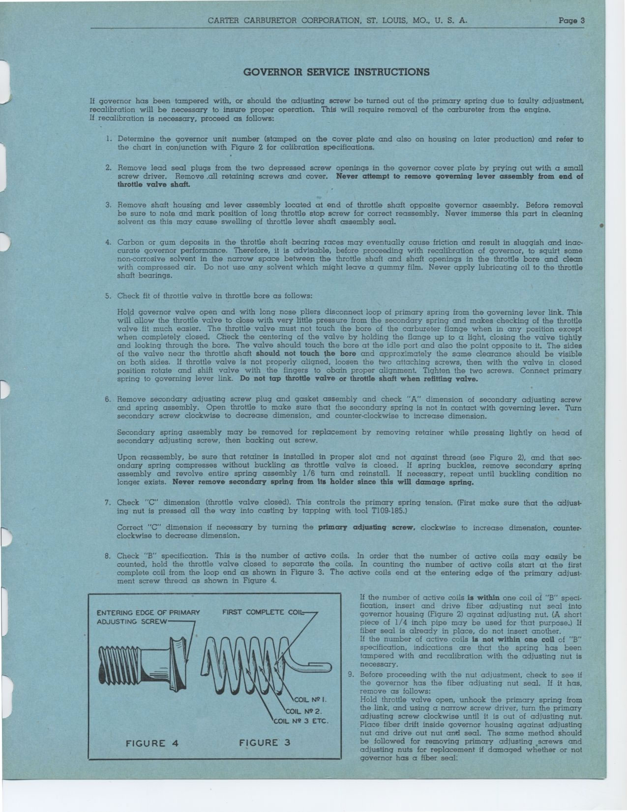
8. Check "B" specification. This is the number of active coils. In
order that the number of active coils may easily be counted, hold the throttle
valve closed to separate the coils. In counting the number of active coils
start at the first complete coil from the loop end as shown in Figure 3. The
active coils end at the entering edge of the primary adjustment screw thread
as shown in Figure 4.
If the number of active coils is within one coil of "B" specification,
insert and drive fiber adjusting nut seal into governor housing (Figure 2)
against adjusting nut. (A short piece of 1/4 inch pipe may be used for that
purpose.) If fiber seal is already in place, do not insert another.
If the number of active coils is not within one coil of "B" specification,
indications are that the spring has been tampered with and recalibration with
the adjusting nut is necessary.
9. Before proceeding with the nut adjustment, check to see if the governor
has the fiber adjusting nut seal. If it has, remove as follows:
Hold throttle valve open, unhook the primary spring from the link, and using
a narrow screw driver, turn the primary adjusting screw clockwise until it
is out of adjusting nut. Place fiber drift inside governor housing against
adjusting nut and drive out nut and seal. The some method should be followed
for removing primary adjusting .screws and adjusting nuts for replacement if
damaged whether or not governor has a fiber seal.
ENTERING EDGE OF PRIMARY FIRST COMPLETE COIL ADJUSTING SCREW
FIGURE 4 FIGURE 3
0