Carburetors for old Dodge Trucks : DODGE CAB OVER ENGINE TRUCK 1942Previous | Home | Next |
 |
and a new tube inserted with tool No. T109-70. Care must be exercised in inserting
new tube which must seat tightly. Use new rivet to complete the installation.
Pump adjustment: Remove air horn assembly, back out throttle adjustment screw,
and place pump operating link int center hole of throttle shaft :ann. Adjustment
call be made by bending horizontal portion of pump connector link, so that
top of pump plunger shaft contacts lip of indicator on pump stroke gauge T109-117S.
Correct travel is %".
Pump stroke adjustable for high or low temperature. Set to longest stroke for
cold weather, shorter stroke for hot weather
driving.
Maximum economy and performance are secured only when breaker n, tilts, spark
plugs, valves and motor timing are setto manufacturer's specifications. After
motor is properly tuned, the following should also be done to insure satisfactory
per-
formance and economy:
(a) Float level must be set as above.
(b) Step-up rod in step-up jet must seat and move freely. When reassembling,
jet must be screwed in tight against
seat.
(c) Step-up piston in body casting should not bind and must
be free of dirt. h ((I) stAlain bolademetering jets nforealtitlude c or high
test fuel.
Cauetion: have not attempt to to insure rrcorrectsfuell(low.11s.
Tl
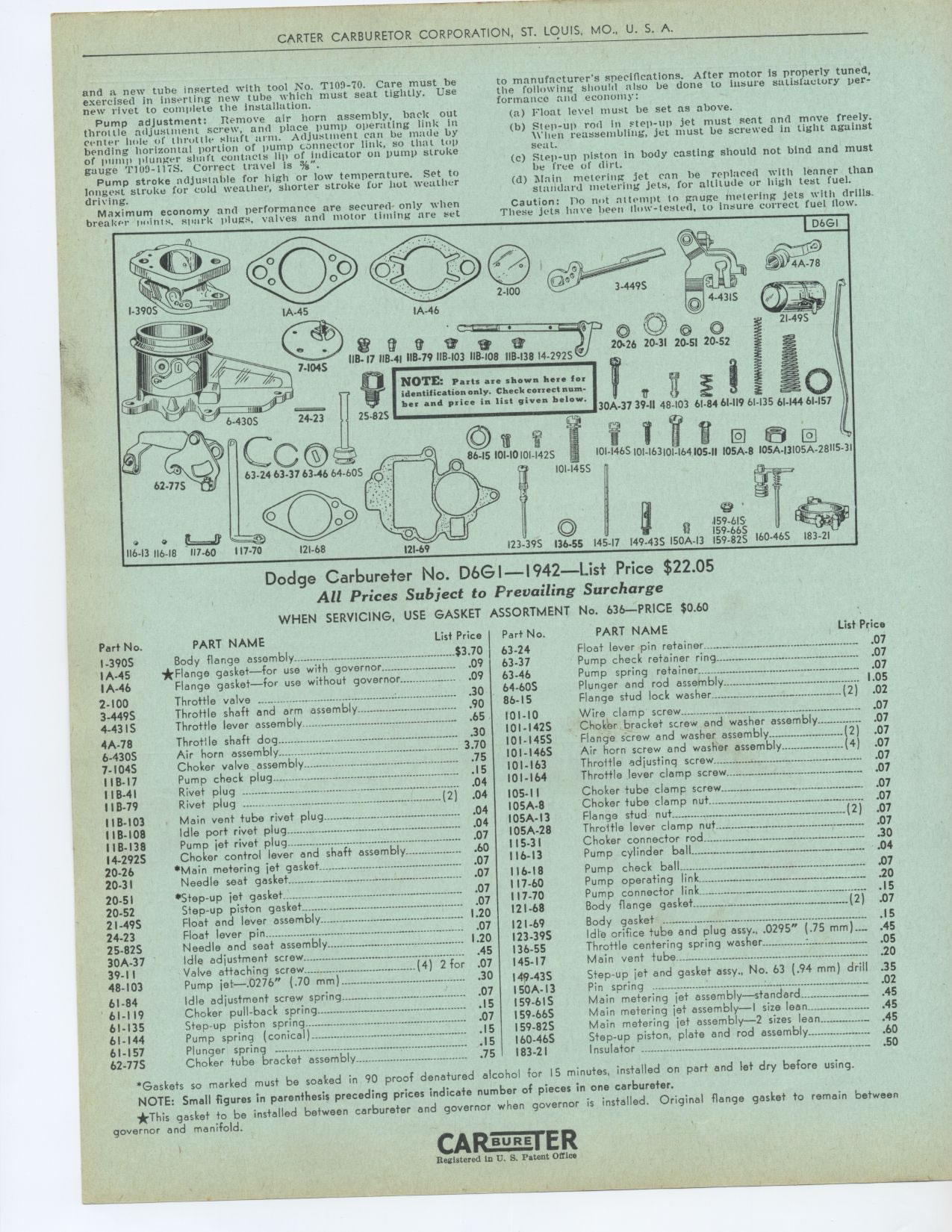
D6G1
4A-78
IA-45
116-13 116-18 117-60
117-70 121-68 121-69 I23-39S
Dodge Carbureter No. DOG I—1942—List Price $22.05
All Prices Subject to Prevailing Surcharge
WHEN SERVICING, USE GASKET ASSORTMENT No. 636—PRICE $0.60
PART NAME List Price
Float lever pin retainer 07
Pump check retainer ring .07
Pump spring retainer. ° 1..07
05
Plunger and rod assembly
Flange stud lock washer -- -- (2) .02
Wire clamp screw •-- -- °---• --•---• .07
24-23 25.82S
e, e
08.17 11B-4l IIB-79 llB-103 118-108 118-138 I4-292S
NOTE: Parts are shown here for identification only. Check correct number and
price in list given below.
86-15 101-10101-142S 101-1465101-163101-164105-II 105A-8105A.I3105A-28115-31
101-1455
Par+ No.
63-24 63-37 63-46 64-60S 86-15 101-10
101-1425 Choker bracket screw and washer assembly Z-- 07
101.1455 Flange screw and washer assembly ( ) .07
-
101-1465 Air horn screw and washer assembly • (4) .07
101-163 Throttle adjusting screw .07
101-164 Throttle lever clamp screw ---- .07
105-I1 Choker tube clamp screw - .07
I05A-8 Choker tube clamp nut 2 07
I05A-I3 Flange stud nut-- ( ) 105A-28 Throttle lever clamp nut- 07
115-31 Choker connector rod_ - .30
116-13 Pump cylinder ball _---•- .04
116-18 Pump check ball 07
117-60 Pump operating link 20
117-70 Pump connector link 07
121-68 Body flange gasket • ..--•-.__. •( ) .
Body gasket
- °• • .I5
136-55 145-17
1 , i
30A-37 39-II 48-103 61.84 61-119 61-135 61-144 61-157
'If i
0
159-6IS
I59-66S
465 183-21 149-43S I50A-13 159-825 160-
Part No. PART NAME List Price
$3.70
I-3905 Body flange assembly •
IA-45 *Flange gasket—for use with governor 09
1A-46 Flange gasket—for use without governor 09
2-100 Throttle valve 90
3-449S Throttle shaft and arm assembly 90
4-431S Throttle lever assembly- _ .65
4A-78 Throttle shaft dog
3.30
6-430S Air horn assembly
-- 70
7-1045 Choker valve assembly
IIB- I7 Pump check plug -- ---------------------• •
-"_ -..
.15
IIB-41 Rivet plug -----2- .04
11B-79 Rivet plug ( )
IIB-103 Main vent tube rivet plug 04
.04
IIB-108 Idle port rivet plug
.. .07
IIB-138 Pump jet rivet plug...
14-2925 Choker control lever and shaft assembly 60
.07
20-26 *Main metering jet gasket
20-31 .07
Needle seat gasket
*Step-up jet gasket .07
20-52 Step-up piston gasket 1..07
07
2I-49S Float and lever assembly • .00
24-23 Float lever pin
1.07
25-82S Needle and seat assembly
30A-37 Idle adjustment screw -----------------• .45
39-I I Valve attaching screw (4) 2 for .07
48-103 Pump let—.0276' ' (.70 mm) 30
.07
61-84 Idle adjustment screw spring 17
61-119 Choker pull-back spring 15
61-135 Step-up piston spring
.15
61-144 Pump spring (conical) ° • .15
61-157 Plunger spring °• • .75
62-77S Choker tube bracket assembly
'Gaskets so marked must be soaked in 90 proof denatured alcohol for 15 minutes,
installed on part and let dry before using. NOTE: Small figures in parenthesis
preceding prices indicate number of pieces in one carbureter.
*This gasket to be installed between carbureter and governor when governor
is installed. Original flange gasket to remain between governor and manifold.
121-69
123-39S Idle orifice tube and plug assy., .0295 .05
136-55 Throttle centering spring washer : 20
145-17 Main vent tube ° I49-43S
150A-13 159.615 159-66S 159-82S I60-46S 183-21
Step-up jet and gasket assy., No. 63 (.94 mm) drill .35 Pin spring .02
•--••-•-•--•--
Main metering jet assembly—standard _ ..45
45
Main metering jet assembly—I size lean
Main metering jet assembly—2 sizes lean _ .45
Step-up piston, plate and rod assembly 60
Insulator
CARnB E R E ten$R