Carburetors for old Dodge Trucks : DODGE TRUCKS 1933Previous | Home | Next |
 |
Form 6098A—Canadian
DODGE TRUCKS—1933 Issue-I September, 1933 - Reprinted December, 1945
C6A2-C6A3-C6A4-
CTA-CTA4-CTB-CTB4
List Price $22.05
Exchange Allowance $3.75
ETB-ETB4
List Price $29.40
Exchange Allowance $5.00
Note: Carbureters used Carbureters used
DODGE TRUCKS 1933
C6A2, C6A3, C6A4 Su 6 439S \
CTA, CTA4, CTB, CTB4 p y )
ETB, ETB4 Superseded by ETRIR /
governor: C6A2, C6A3, C6A4, CTA, CTA4. on motors with governor: CTB, CTB4,
ETB, ETB4.
on motors without
Stroke
Bore and
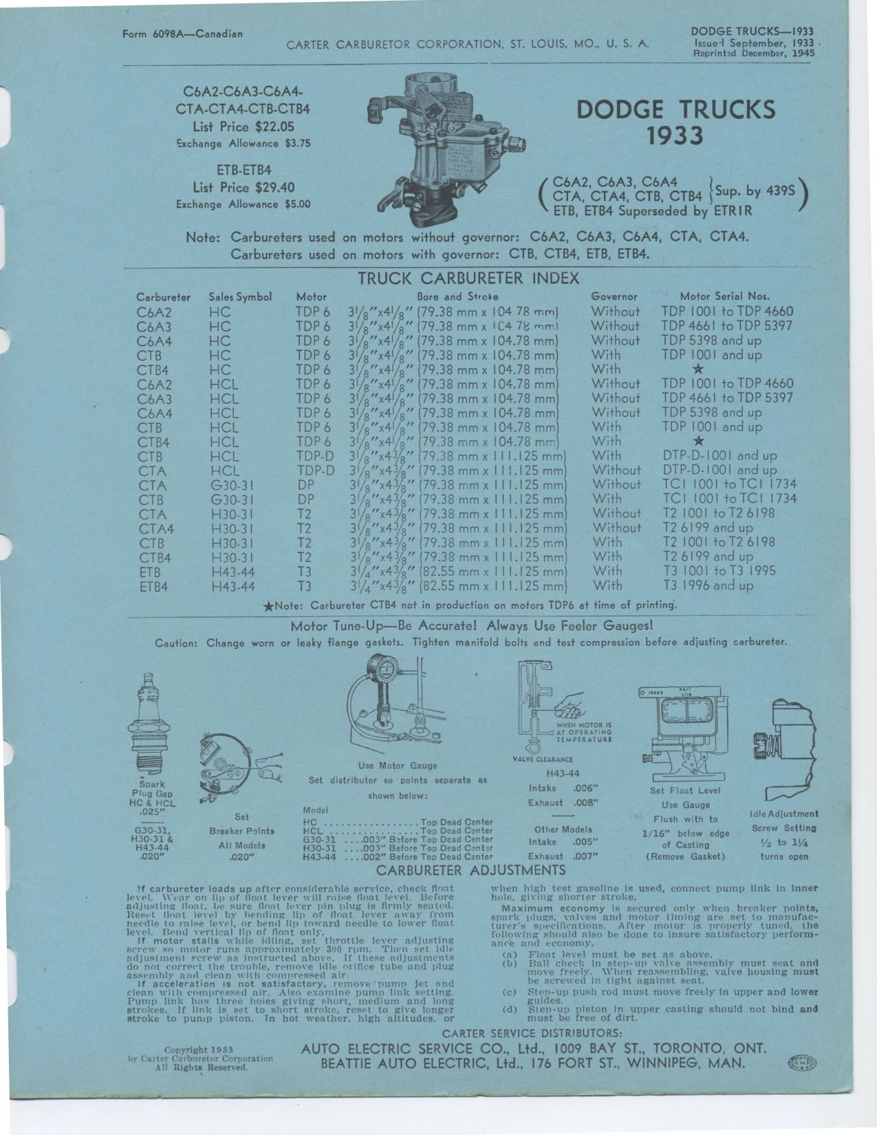
TRUCK CARBURETER INDEX
C6A2 HC TDP 6 31/8"x41/8" (79.38 mm
C6A3 HC TDP 6 31/8"x41/8" (79.38 mm
C6A4 HC TDP 6 31/8"x41/8" (79.38 mm
CTB HC TDP 6 31/8"x41/g" (79.38 mm
CTB4 HC TDP 6 31/8"x41/8" (79.38 mm
C6A2 HCL TDP 6 31/9"x41/8" (79.38 mm
C6A3 HCL TDP6 31/8''x41/81' (79.38 mm
C6A4 HCL TDP 6 31/8"x41/8" (79.38 mm
CTB HCL TDP 6 31/8"x41/8" (79.38 mm
CTB4 HCL TDP 6 31/8"x41/g" (79.38 mm
CTB HCL TDP-D 31/8"x43/8" (79.38 mm
CTA HCL TDP-D 31/8"x43/8" (79.38 mm
CTA G30-31 DP 3I/8"x43/8" (79.38 mm
CTB G30-31 DP 3!/"x43/8" (79.38 mm
CTA H30-31 T2 31/8"x43/g" (79.38 mm
CTA4 H30-31 T2 31/8"x43/g" (79.38 mm
CTB H30-31 T2 31/8"x43/8" (79.38 mm
CTB4 H30-31 T2 31/9"x43/8" (79.38 mm
ETB H43-44 T3 31/4"x43/8" (82.55 mm
ETB4 H43-44 T3 31/4"x43/g" (82.55 mm
x 104 78 mm)
x IC4 78 mmi
x 104.78 mm)
x 104.78 mm)
x 104.78 mm)
x 104.78 mm)
x 104.78 mm)
x 104.78 mm)
x 104.78 mm)
x 104.78 mm)
x 111.125mm) x I 11.125 mm) x 111.125mm) x 111.125mm) x 111.125mm) x 111.125
mm) x 111.125mm) x 111.125mm) r. 111.125mm) x 111.125mm)
Governor Motor Serial Nos.
Without TDP 1001 to TDP 4660
Without TDP 4661 to TDP 5397
Without TDP 5398 and up
With TDP 1001 and up
With *
Without TDP 1001 to TDP 4660
Without TDP 4661 to TDP 5397
Without TDP 5398 and up
With TDP 1001 and up
With *
With DTP-D-1001 and up
Without DTP-D-1001 and up
Without TC 1 1001 to TC 1 1734
With TC 11001 to TC 11734
Without T2 1001 to T2 6198
Without T2 6199 and up
With T2 1001 to T2 6198
With T2 6199 and up
With T3 1001 to T3 1995
With T3 1996 and up
Carburetor Sales Symbol Motor .
*Note: Carbureter CTB4 not in production on motors TDP6 at time of printing.
Motor Tune-Up—Be Accurate! Always Use Feeler Gauges!
Caution: Change worn or leaky flange gaskets. Tighten manifold bolts and test
compression before adjusting carbureter.
VALVE CLEARANCE
H43-44
Intake .006"
Exhaust .008" Model _
HC Top Dead Center
HCL ..Top Dead Center Other Models
G30-31 ....003" Before Top Dead Center Intake .005" H30-31 ....003" Before
Top Dead Center
H43-44 ....002" Before Top Dead Center Exhaust .007"
CARBURETER ADJUSTMENTS
Spark Plug Gap HC & HCL .025"
G30-31, H30-31 & H43-44 .020"
Set
Breaker Points
All Models
.020"
Use Motor Gauge
Set distributor so points separate as
shown below:
Idle Adjustment
1/16" below edge Screw Setting
of Casting V2 to 1%q
(Remove Gasket) turns open
Set Float Level We Gauge Flush with to
If carbureter loads up after considerable service, check float level. \\-onr
on lip of Iloat lever will raise float level. Before adjusting neat, be sure
float lever pin plug is firmly seated. Heset float level by bending lip of
float lever away from needle to raise level, or bend lip toward needle to lower
float level. Pend vertical lip of float only.
If motor stalls while idling, set throttle lever adjusting screw so motor runs
approximately 300 rpm. Then set idle adjustment screw as instructed above.
If these adjustments do not correct the trouble, remove idle orifice tube and
plug assembly and clean with compressed air.
If acceleration is not satisfactory, remove pump jet and clean with compressed
air. Also examine pump link setting. Pump link line three holes giving short,
medium and long strokes. If link is set to short stroke, reset to give longer
stroke to pump piston. In hot weather, high altitudes, orwhen high test gasoline
is used, connect pump link in inner hole, giving shorter stroke.
Maximum economy is secured only when breaker points, spark plugs, valves and
motor tinting are set to manufacturer's specifications. After motor is properly
tuned. the following should also be clone to insure satisfactory performance
and economy.
(a) Float level must be set as above.
(b) Ball check in step-up valve assembly must seat and move freely. \\'lien
reassembling, valve housing must be screwed in tight against seat.
(c) Step-up push rod must move freely in upper and lower guides.
(d) Step-up piston in upper casting should not bind and must be free of dirt.
Copyright 1933