|
Form 6559A—Canadian
CARTER CARBURETOR CORPORATION, ST. LOUIS, MO., U. S. A.
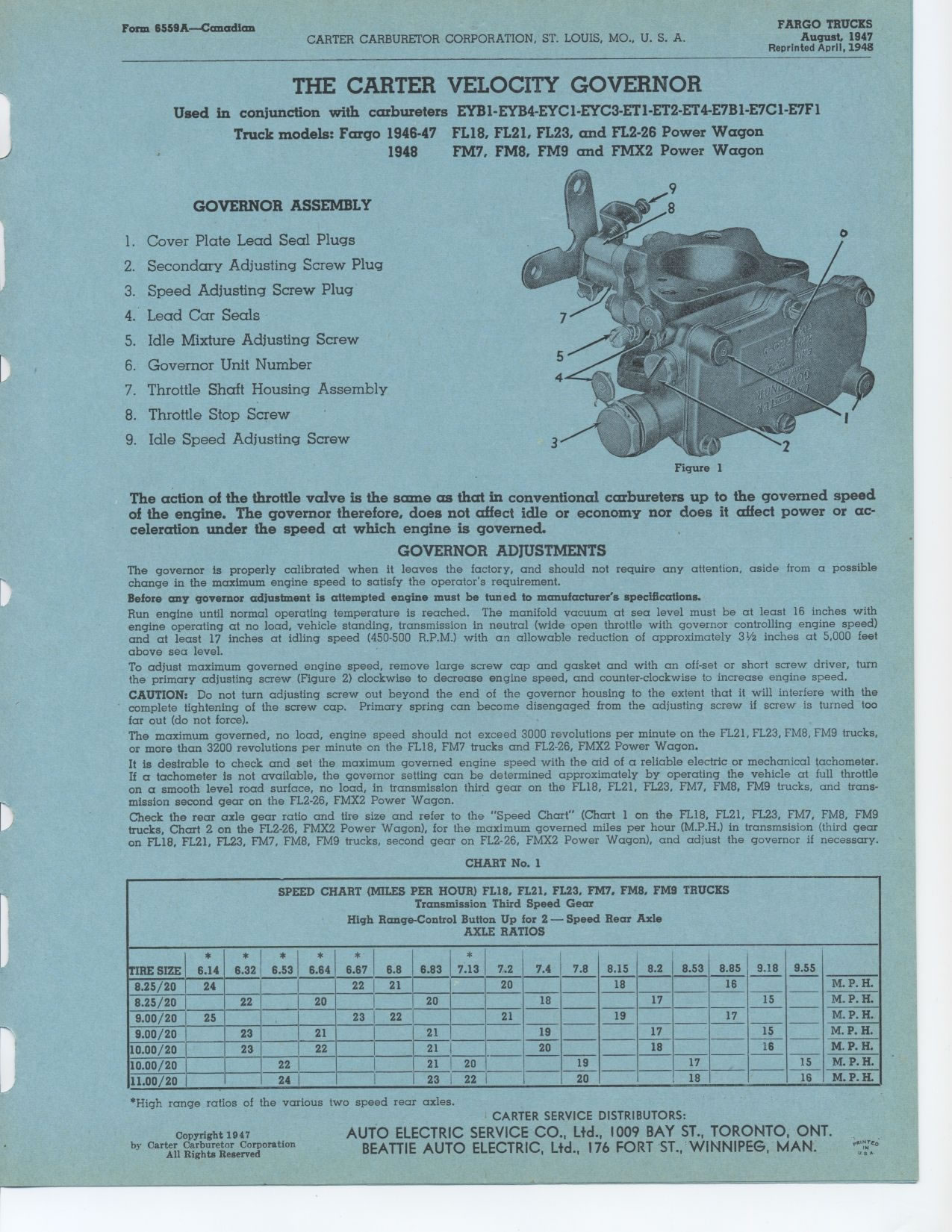
FARGO TRUCKS GOVERNOR ASSEMBLY
August, 1947
Reprinted April, 1948
THE CARTER VELOCITY GOVERNOR
Used in conjunction with carbureters EYB1-EYB4-EYCI-EYC3-ET1-ET2-ET4-E7B1-E7C1-E7F1
Truck models: Fargo 1946-47 FL18, FL21, FL23, and FL2-26 Power Wagon
1948 FM7, FM8, FM9 and FMX2 Power Wagon
1. Cover Plate Lead Seal Plugs
2. Secondary Adjusting Screw Plug
3. Speed Adjusting Screw Plug
4. Lead Car Seals
5. Idle Mixture Adjusting Screw
6. Governor Unit Number
7. Throttle Shaft Housing Assembly
8. Throttle Stop Screw
9. Idle Speed Adjusting Screw
The action of the throttle valve is the some as that in conventional carbureters
up to the governed speed of the engine. The governor therefore, does not
affect idle or economy nor does it affect power or ac-
celeration under the speed at which engine is governed. GOVERNOR ADJUSTMENTS
The governor is properly calibrated when it leaves the factory, and should
not require any attention, aside from a possible change in the maximum engine
speed to satisfy the operator's requirement.
Before any governor adjustment is attempted engine must be tuned to manufacturer's
specifications.
Run engine until normal operating temperature is reached. The manifold vacuum
at sea level must be at least 16 inches with engine operating at no load,
vehicle standing, transmission in neutral (wide open throttle with governor
controlling engine speed) and at least 17 inches at idling speed (450-500
R.P.M.) with an allowable reduction of approximately 31/2 inches at 5,000
feet above sea level.
To adjust maximum governed engine speed, remove large screw cap and gasket
and with an off-set or short screw driver, turn the primary adjusting screw
(Figure 2) clockwise to decrease engine speed, and counter-clockwise to increase
engine speed. CAUTION: Do not turn adjusting screw out beyond the end of
the governor housing to the extent that it will interfere with the complete
tightening of the screw cap. Primary spring can become disengaged from the
adjusting screw if screw is turned too far out (do not force).
The maximum governed, no load, engine speed should not exceed 3000 revolutions
per minute on the FL21, FL23, FM8, FM9 trucks, or more than 3200 revolutions
per minute on the FL18, FM7 trucks and FL2-26, FMX2 Power Wagon.
It is desirable to check and set the maximum governed engine speed with the
aid of a reliable electric or mechanical tachometer. If a tachometer is not
available, the governor setting can be determined approximately by operating
the vehicle at full throttle on a smooth level road surface, no load, in
transmission third gear on the FL18, FL21, FL23, FM7, FM8, FM9 trucks, and
trans-mission second gear on the FL2-26, FMX2 Power Wagon.
Check the rear axle gear ratio and tire size and refer to the "Speed
Chart" (Chart 1 on the FL18, FL21, FL23, FM7, FM8, FM9 trucks, Chart
2 on the FL2-26, FMX2 Power Wagon), for the maximum governed miles per hour
(M.P.H.) in transmsision (third gear on FL18, FL21, FL23, FM7, FM8, FM9 trucks,
second gear on FL2-26, FMX2 Power Wagon), and adjust the governor if necessary.
CHART No. 1
SPEED CHART (MILES PER HOUR) FL18, FL21, FL23, FM7, FM8, FM9 TRUCKS
Transmission Third Speed Gear
High Range-Control Button Up for 2 — Speed Rear Axle
AXLE RATIOS
TIRE SIZE * * * i * * i * 7.2 7.4 7.8 8.15 8.2 8.53 8.85 9.18 9.55
6.14 6.32 6.53 6.64 6.67 6.8 6.83 7.13
M. P. H.
8.25/20 24 22 21 20 18 16
8.25/20 22 20 20 18 17 15 M.P.H.
9.00/20 25 23 ~ 22 21 19 17 M.P.H.
9.00/20 23 21 21 19 17 15 M.P.H.
I
1 0.00/20 23 22 21 20 18 16 M.P.H.
17 15 M.P.H.
10.00/20 1 22 21 20 19
11 00/20 1 24 1 23 22 20 18 16 M.P.H.
I
*High range ratios of the various two speed rear axles.
Figure 1
Copyright 1947
|