|
Page 2 CARTER CARBURETOR CORPORATION, ST. LOUIS, MO., U. S.
A.
CARBURETER ADJUSTMENTS
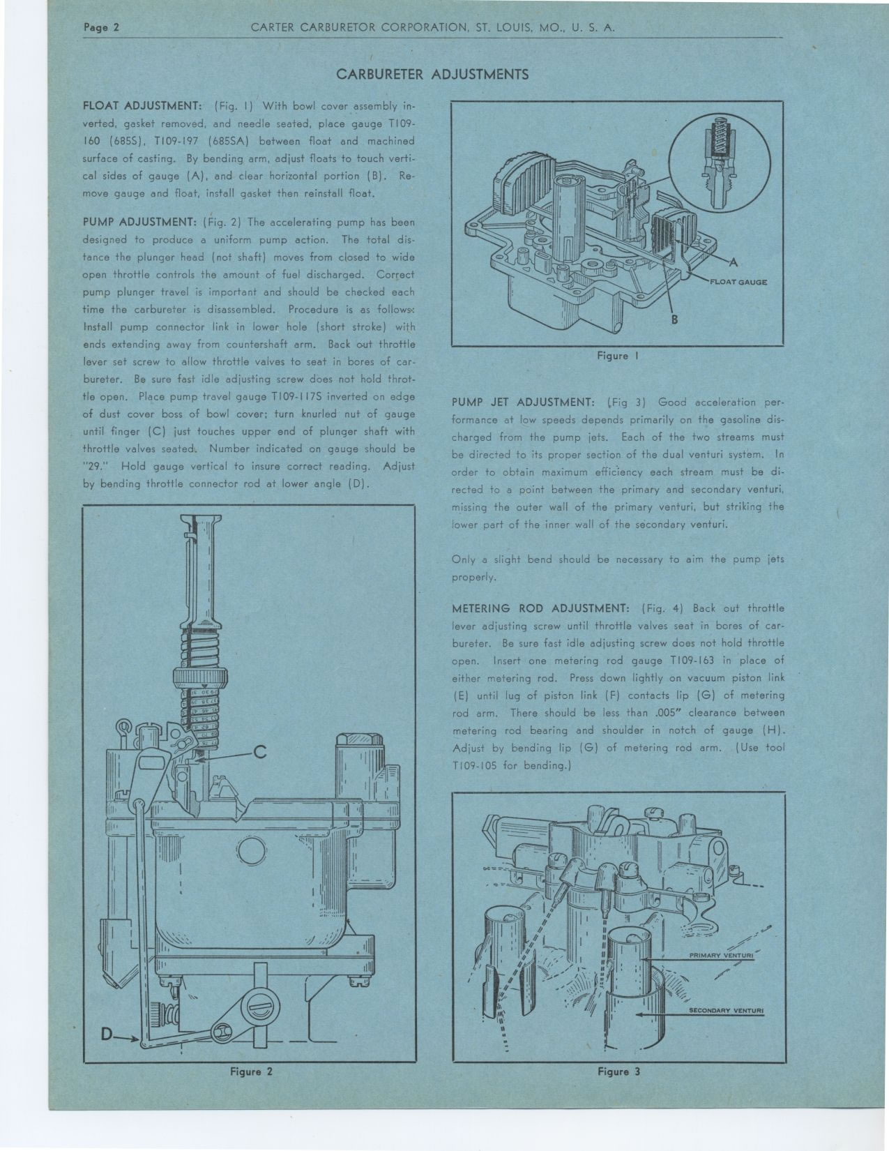
FLOAT ADJUSTMENT: (Fig. I) With bowl cover assembly inverted, gasket removed,
and needle seated, place gauge T109-160 (685S), T109-197 (685SA) between
float and machined surface of casting. By bending arm, adjust floats to touch
vertical sides of gauge (A), and clear horizontal portion (B). Re-move gauge
and float, install gasket then reinstall float.
PUMP ADJUSTMENT: (Fig. 2) The accelerating pump has been designed to produce
a uniform pump action. The total distance the plunger head (not shaft) moves
from closed to wide open throttle controls the amount of fuel discharged.
Correct pump plunger travel is important and should be checked each time
the carbureter is disassembled. Procedure is as follows.: Install pump connector
link in lower hole (short stroke) with ends extending away from countershaft
arm. Back out throttle lever set screw to allow throttle valves to seat in
bores of carbureter. Be sure fast idle adjusting screw does not hold throttle
open. Place pump travel gauge T109-I 17S inverted on edge of dust cover boss
of bowl cover; turn knurled nut of gauge until finger (C) just touches upper
end of plunger shaft with throttle valves seated. Number indicated on gauge
should be "29." Hold gauge vertical to insure correct reading.
Adjust by bending throttle connector rod at lower angle (D).
Figure 2
Figure I
PUMP JET ADJUSTMENT: (Fig 3) Good acceleration performance at low speeds
depends primarily on the gasoline discharged from the pump jets. Each of
the two streams must be directed to its proper section of the dual venturi
system. In order to obtain maximum efficiency each stream must be directed
to a point between the primary and secondary venturi, missing the outer wall
of the primary venturi, but striking the lower part of the inner wall of
the secondary venturi.
Only a slight bend should be necessary to aim the pump jets properly.
METERING ROD ADJUSTMENT: (Fig. 4) Back out throttle lever adjusting screw
until throttle valves seat in bores of carbureter. Be sure fast idle adjusting
screw does not hold throttle open. Insert one metering rod gauge T109-163
in place of either metering rod. Press down lightly on vacuum piston link
(E) until lug of piston link (F) contacts lip (G) of metering rod arm.
There should be less than .005" clearance between metering rod bearing
and shoulder in notch of gauge (H). Adjust by bending lip (G) of metering
rod arm. (Use tool T109-105 for bending.)
Figure 3
|