|
CARTER CARBURETOR CORPORATION, ST. LOUIS, MO., U. S. A. Page
3
Figure 4
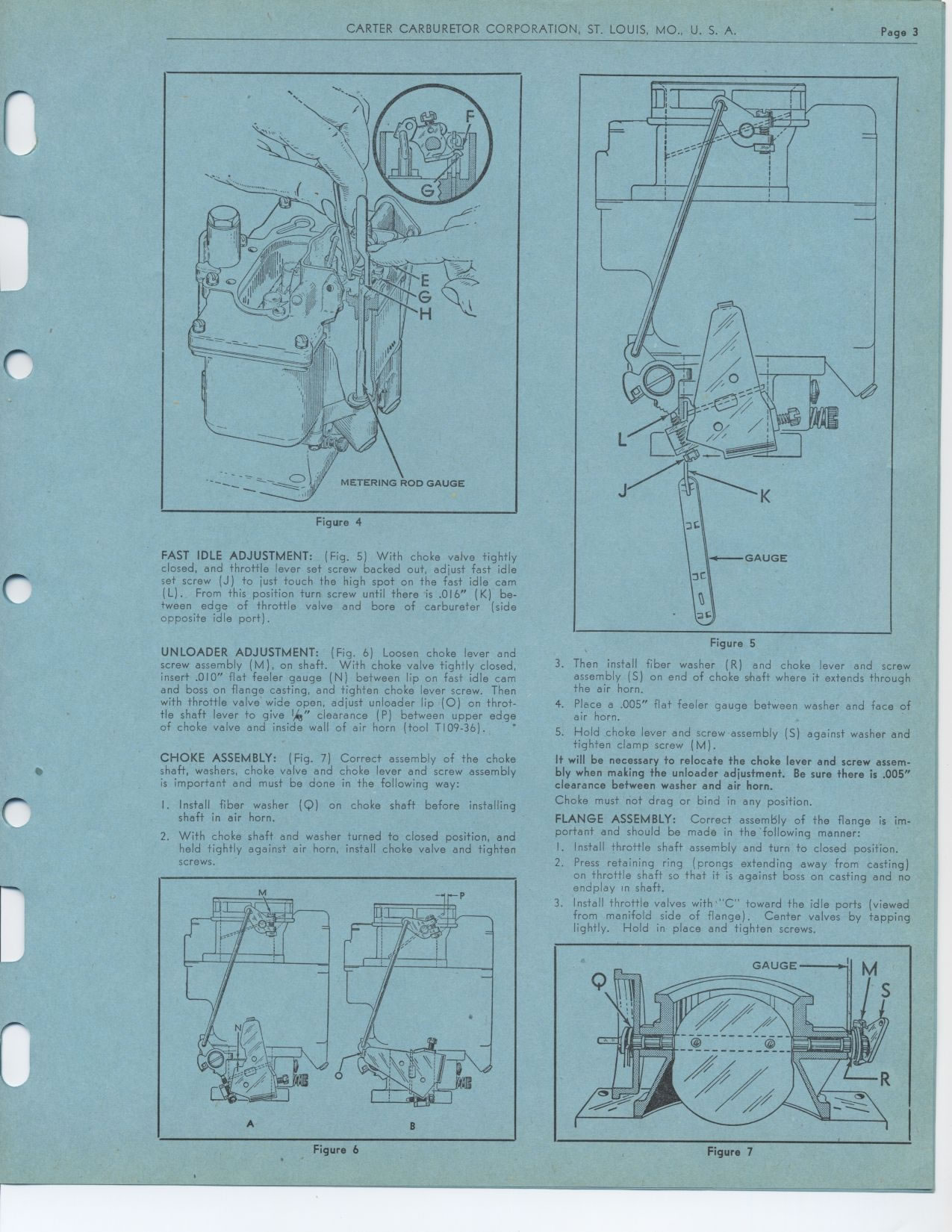
FAST IDLE ADJUSTMENT: (Fig. 5) With choke valve tightly closed, and throttle
lever set screw backed out, adjust fast idle set screw (J) to just touch
the high spot on the fast idle cam (L). From this position turn screw until
there is .016" (K) between edge of throttle valve and bore of carbureter
(side opposite idle port).
UNLOADER ADJUSTMENT: (Fig. 6) Loosen choke lever and screw assembly (M),
on shaft. With choke valve tightly closed, insert .010" flat feeler
gauge (N) between lip on fast idle cam and boss on flange casting, and tighten
choke lever screw. Then with throttle valve wide open, adjust unloader lip
(0) on throttle shaft lever to give 4" clearance (P) between upper edge
of choke valve and inside wall of air horn (tool T109-36).
CHOKE ASSEMBLY: (Fig. 7) Correct assembly of the choke shaft, washers, choke
valve and choke lever and screw assembly is important and must be done in
the following way:
I. Install fiber washer (Q) on choke shaft before installing shaft in air
horn.
2. With choke shaft and washer turned to closed position, and held tightly
against air horn, install choke valve and tighten screws.
Figure 6
Figure 5
3. Then install fiber washer (R) and choke lever and screw assembly (S)
on end of choke shaft where it extends through the air horn.
4. Place a .005" flat feeler gauge between washer and face of air horn.
5. Hold choke lever and screw assembly (S) against washer and tighten clamp
screw (M).
It will be necessary to relocate the choke lever and screw assembly when
making the unloader adjustment. Be sure there is .005" clearance between
washer and air horn.
Choke must not drag or bind in any position.
FLANGE ASSEMBLY: Correct assembly of the flange is important and should be
made in the following manner: I Install throttle shaft assembly and turn
to closed position.
2. Press retaining ring (prongs extending away from casting)
on throttle shaft so that it is against boss on casting and no
endplay In shaft.
3. Install throttle valves with'''C" toward the idle ports (viewed from
manifold side of flange). Center valves by tapping lightly. Hold in place
and tighten screws.
Figure 7
A B
|